 Loading... Please wait...
Projects
Bridges
-
Overview
Bridge structures in many countries around the world have used GEOKON sensors for measuring key parameters such as strain, displacement, force, temperature, inclination, alignment and settlement. Sensors are installed permanently for long-term health monitoring, temporarily for load testing and/or to ensure safe working conditions during repair or strengthening. Internet-accessible data acquisition systems ensure that any significant change in the condition or behavior of the structure is logged, reported and efficiently monitored.
Case Histories
-
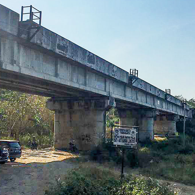
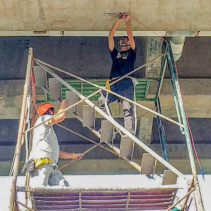
BH-355 Bridge and Landslide Monitoring
Cignea, West Java, Indonesia
Project Summmary and Objectives: Due to recent landslides in the area, caused by seismic activity, there was an immediate need to monitor the movement of the ground in and around bridge number BH-355.
Visible fracture in the ground running parallel to the bridge caused concern for the integrity of the crucial railway bridge. A complete monitoring system consisting of several multilevel IPI's, parallel to the bridge, provided a real-time alert in the event of ground movement to the nearby stations. The ground movement was complemented by bridge instrumentation to ensure the integrity of the bridge was maintained.
In total 54 sensors sensors were installed between the bridge and ground, with a single data acquisition unit, with online software provided by Strainstall's Smart Asset Management System (SAMS).
For additional information, please contact: Damian Griffiths | Strainstall Middle East (SME-Testing)
-
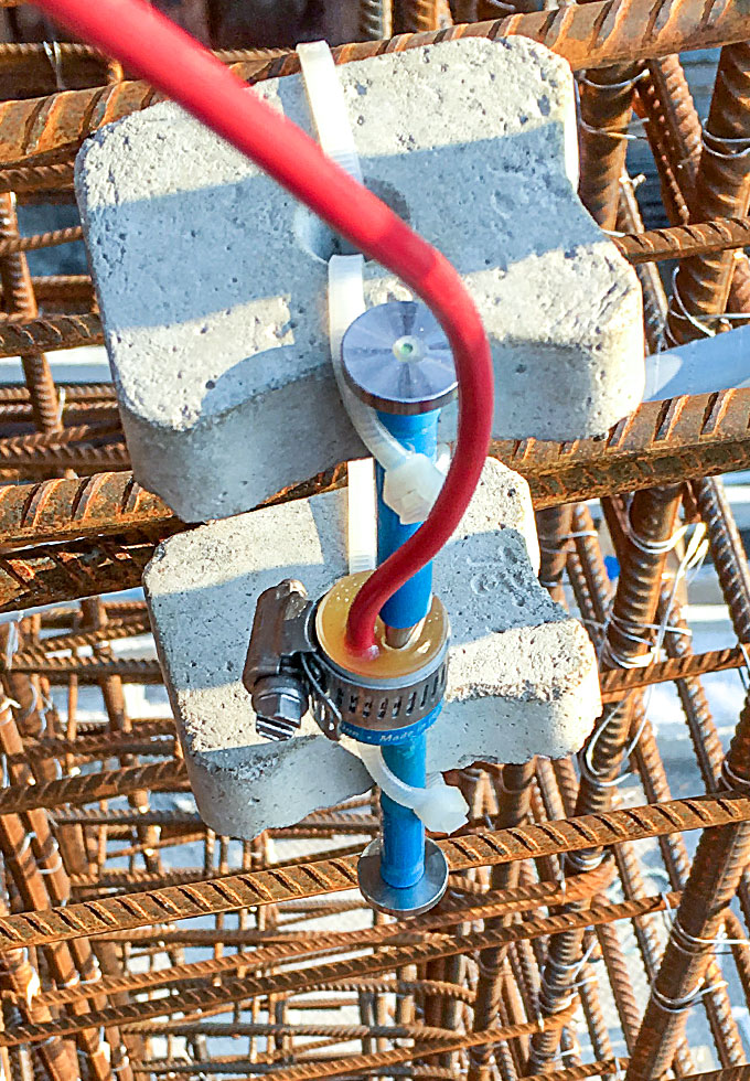
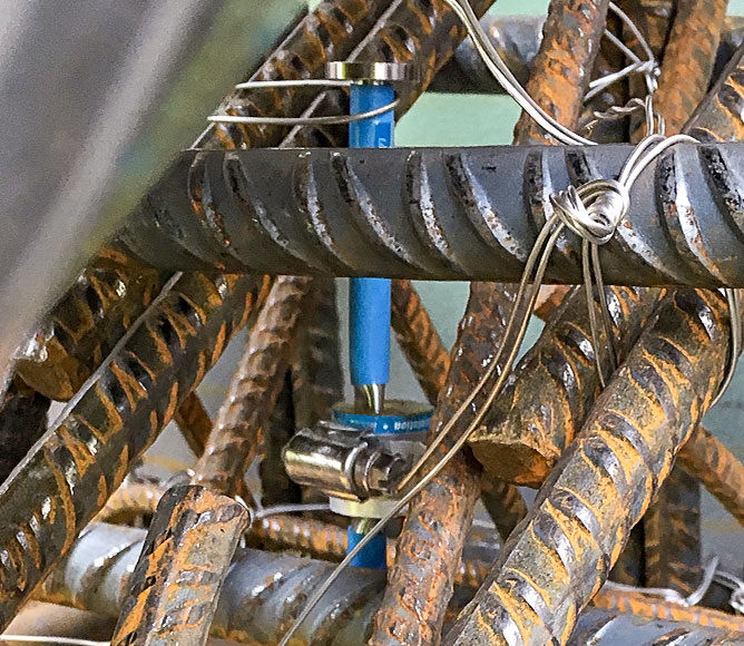

Mersey Gateway Bridge
Widnes, United Kingdom
The Mersey Gateway Bridge carries a dual three lane highway across the Mersey Estuary between Runcorn and Widnes with a dual 3-lane approach between Widnes Loops and the Astmoor/Bridge water Viaduct.
The Main Crossing consists of an approximately 2.25 km long structure which includes a three pylon stayed Main Bridge approximately 1 km long, the 550 m long South Approach Viaduct and the 700 m long North Approach Viaduct.
The stay cables are formed from parallel strands in a central plane. Overall width of the deck varies between approximately 32 m and 45 m. The deck is post tensioned longitudinally by internal bonded tendons in the Approach Viaducts and external unbounded tendons in the Main Bridge. In addition, transverse post tensioning is provided in the top slab.
The deck is monolithic with the Central Pylon and supported on sliding bearings at the North Pylon and South Pylon and the Approach Viaduct Piers. The pylons are hollow reinforced concrete sections with fabricated steel anchorage boxes in the stay anchorage zones. The Approach Viaducts piers are hollow reinforced concrete elements.
Instrumentation used: Model 4200 Concrete Embedment Strain Gauges
The purpose of the the GEOKON instrumentation installed is to monitor the strain in the concrete over the lifetime of the structure. The sensors are installed at multiple points within the bridge deck, the pylons and the piers supporting the deck.
Project submitted courtesy of James Fisher Testing Services, United Kingdom.
-
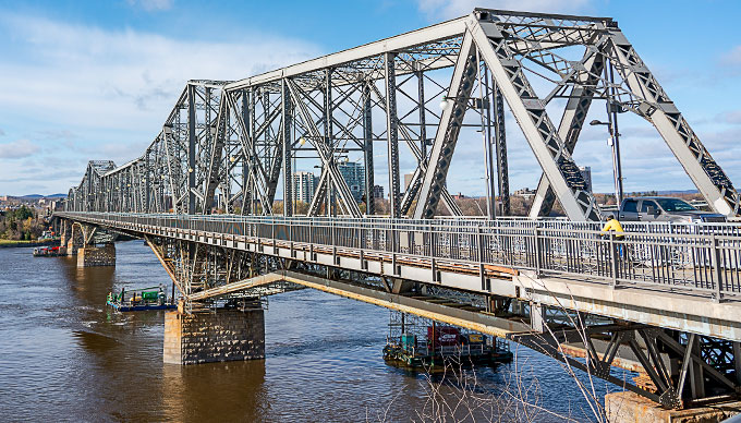
Alexandra Bridge
Ottawa, Canada
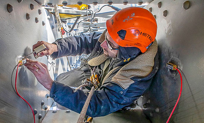
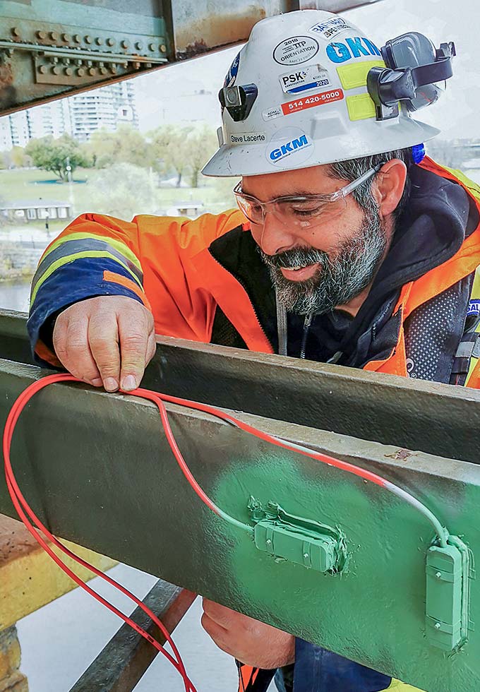
Project Summmary and Objectives: Long-term structural health monitoring of a cantilever truss bridge near the parliament hill of Canada in Ottawa.
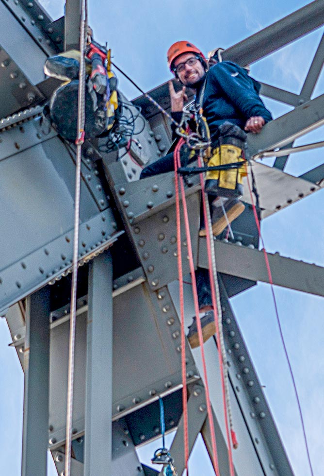
A total of 88 Model 4100 Spot Weldable Strain Gauges were used and the gauges were connected, using 2160 m of Model 02-187V3 red cable, to a central ADAS for dynamic measurements composed of CSI Granite Modules.
GKM Consultants offers turnkey, custom solutions for structural health monitoring.
Project submitted courtesy of GKM Consultants, Sainte-Julie (QC), Canada | Case Summary
-
Structural Health Monitoring of an Overpass
Canada
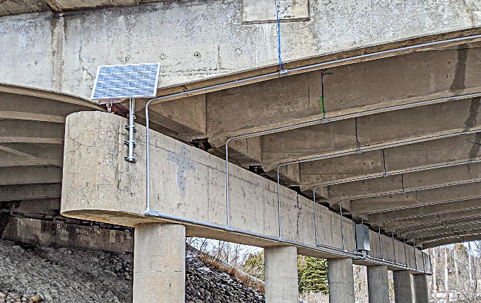
GKM Consultants is proud to have been mandated by a nationally-leading engineering firm to develop, commission and install a state-of-the-art structural health monitoring system for an aging highway overpass in Canada. This monitoring system will help extend the lifespan of the structure by providing real-time, high-quality strain data.
72 vibrating wire strain gauges were installed on the girders of the structure. While foil strain gauges are a typical choice for high-speed data acquisition, their output tends to drift over time. The enhanced stability of vibrating wire strain gauges makes them a better choice for long term monitoring despite their lower bandwidth. Strain gauges are often attached to a structure using an epoxy glue but this method is not compatible with a cold-weather installation and degradation of the glue-concrete interface renders comparison of measurements unreliable after a few years.
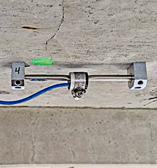
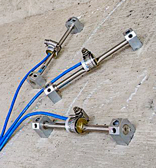
The preferred method for long-term monitoring is to use drop-in concrete anchors, but standard anchors are long with respect to the thickness of the girder’s web. Therefore, the unique conditions of this structure required the development of custom anchors with the collaboration of GEOKON.
The strain gauges were installed in rosette patterns to measure both strain and shear.
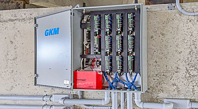
The data acquisition system is built upon Campbell Scientific’s new GRANITE platform. The system performs automatic long-term static measurements of the structure as well as the collection of periodic bursts of dynamic data to track fatigue in individual girders. The system can also be triggered manually with a mechanical switch when performing on-site tests to measure the effects of loading from live load test trucks.
Installation was performed to the highest standards by GKM Consultants’ team, running more than 2 km of instrument cables in conduits. This attention to detail will help extend the lifespan of the system for as long as needed until the overpass undergoes major maintenance.
GKM Consultants offers turnkey, custom solutions for structural health monitoring and is proud of helping our government ministries manage the safety of their infrastructure.
For additional information, please visit: GKM Consultants | Case Summary
-
Structural Health Monitoring System for the Burlington-Bristol Bridge
Bristol, Pennsylvania, USA
Burlington, New Jersey, USA
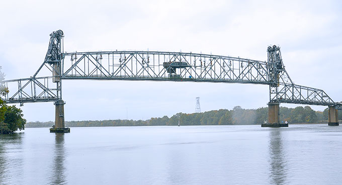
Pennoni Associates Inc. designed and installed an efficient structural health monitoring (SHM) system capable of providing information regarding the operational and structural performance of the Burlington-Bristol Bridge. The owner, Burlington County Bridge Commission, has adopted the goal of indefinite preservation for their signature structures and has moved to augment conventional engineering practice with the latest sensing and simulation technology to ensure all decisions are made from the most informed standpoint possible. The Burlington-Bristol Bridge is a signature long-span bridge that crosses the Delaware River to connect Bristol, PA and Burlington City, NJ. The bridge is 3,144 feet in total length with a 540-foot main-span through truss that lifts 75 feet vertically to accommodate large ships.
To assist in the design and development of the SHM system, a detailed 3D finite element model of the entire span was constructed and used to design an efficient and effective instrumentation plan.
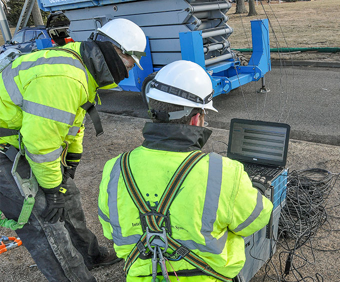
The SHM system for the BBB utilizes a wide variety of sensors and hardware to achieve the measurement objectives. GEOKON Model 4000 and Model 4150 vibrating wire strain gages are used to provide measurements on load levels of critical members, seating force of the movable span, and live load force magnitudes.
For additional information, please visit the Case Summary
-
Emergency Inspection and Monitoring of Bridge 1-813, I-495 over the Christina River
Wilmington, Delaware, USA
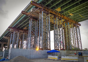
Pennoni Associates Inc. and Pennoni were responsible for the hands-on emergency inspection of the superstructure and substructure of Spans 11 through 14 and Pier 15 of Bridge 1-813. The bridge, located in Wilmington, Delaware, is comprised of twin structures carrying northbound and southbound Interstate 495. Independent multi-beam superstructures and independently supported hammerhead piers, under each half of the structure, carry 90,000 vehicles per day.
Within 40 minutes of being alerted to the problem by DelDOT, Pennoni Associates Inc. engineers were onsite to assess the condition of the bridge. Transverse rotations up to 4 percent from their original position were observed in Piers 11 through 14 causing the median barriers to be vertically out of alignment by as much as 17 inches, which was visible from the roadway. It was later determined that this rotation was a result of a large earth embankment (estimated at 50,000 tons) placed immediately adjacent to the structure, causing compression of the underlying soft soils and lateral pressure on the bridge foundations.
The bearings, field splices, cross frame connections, deck joints, top of deck, hammerhead pier caps, and pier columns were all inspected hands-on to assess any damage caused by the global rotations/movement of the structure and measurements were collected to document these rotations/movements. In addition, open pits were excavated along the south faces of the foundations of Piers 11 through 14 exposing the full height of the footing and approximately 18-inches of the piles beneath the footing for inspection.
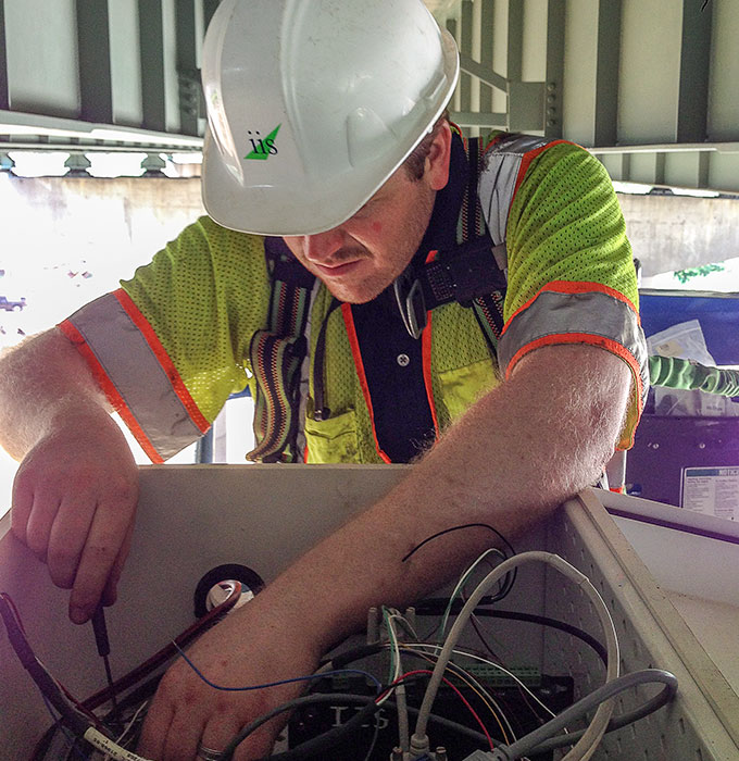
GEOKON Model 6350 Tiltmeters were installed on Piers 10 through 15 to continuously monitor the pier rotations via real-time data collection using dataloggers and multiplexers. Data was collected within 12 hours of the initial call from DelDOT. Duties included extensive coordination with DelDOT’s Bridge Management section, coordination with access equipment providers, oversight and management of all field operations (inspection and monitoring), hands-on inspection of Spans 11 through 14 and pier foundations/piles, supported DelDOT’s Survey section with collecting survey points on the structure, attendance and participation at internal DelDOT coordination meetings, preparation of interim daily reports of conditions found, and preparation of a final comprehensive emergency inspection report.
The bridge was re-opened to traffic within two months. During construction of the temporary repairs, GEOKON Model 4000 Strain Gages were installed on the temporary post tensioning bars to monitor the change in strain in these elements as the structure was lifted and rotated back into alignment. During the lifting and realignment process dynamic data was required so the system was reconfigured using 8-channel dynamic vibrating-wire analyzers that were used to collect data from the tiltmeters and strain gages at a 20Hz sampling rate.
Following completion of the permanent repairs, Pennoni Associates Inc. has installed a long-term monitoring system consisting of 48 GEOKON Model 6350 Tiltmeters. Five remote data acquisition units power and read the tiltmeters. The remote units are powered by a solar panel/battery combination. Data is transmitted to a base station via a spread spectrum radio every 15 minutes. The data stored on the datalogger is then transmitted simultaneously to DelDOT and Pennoni Associates Inc. by two separate Sierra Wireless cellular modems.
For additional information, please visit the Case Summary
-
Bridge Monitoring System Study
New Hope, Pennsylvania, USA
Lambertville, New Jersey, USA
Riverton, Pennsylvania, USA
Belvidere, New Jersey, USA
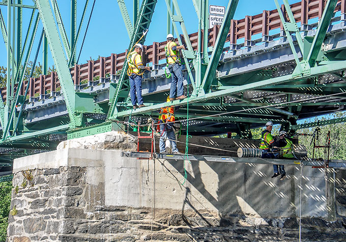
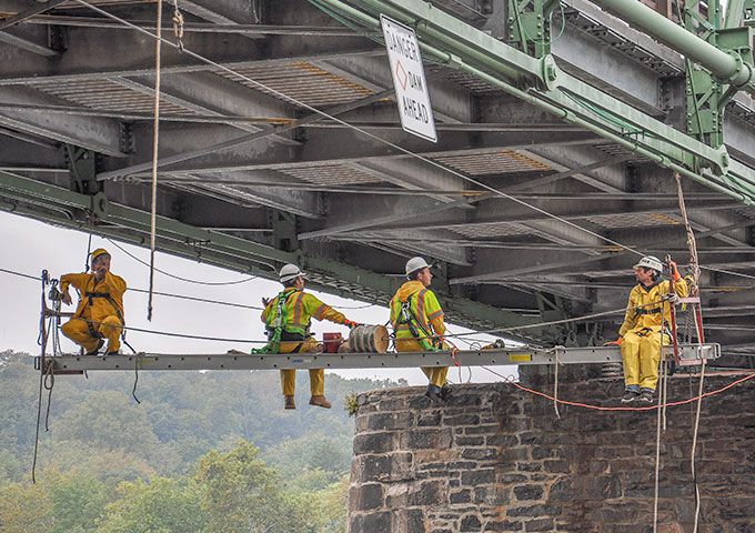
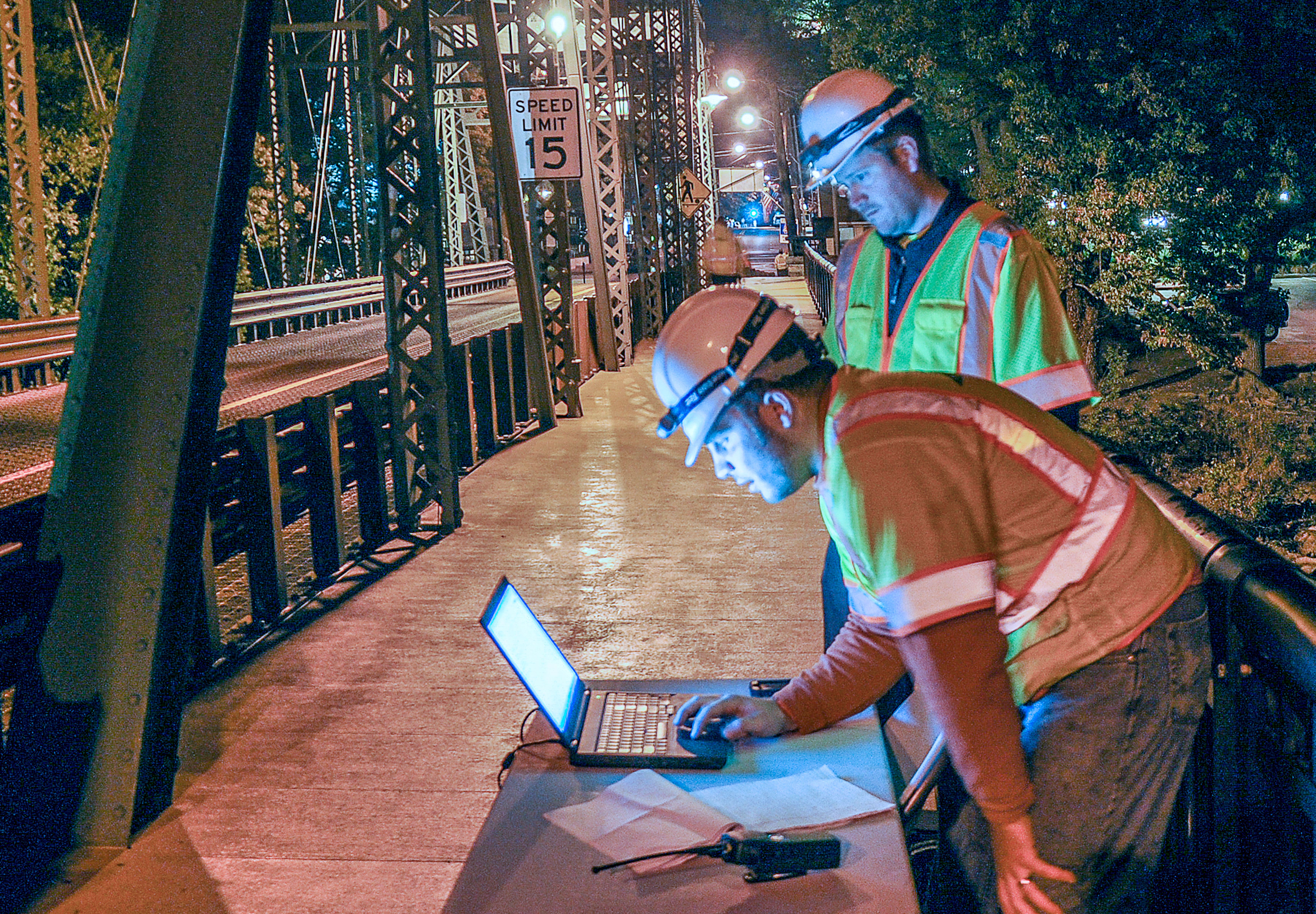
The Delaware River Joint Toll Bridge Commission (DRJTBC) owns and operates 20 bridges over the Delaware River between New Jersey and Pennsylvania. Among the oldest structures in its jurisdiction are the New Hope-Lambertville Toll-Supported Bridge, and the Riverton–Belvidere Toll-Supported Bridge. Both of these through trusses are more than 100 years old and are currently posted for 4 tons and 8 tons, respectively. These bridges were selected by DRJTBC to be used in a Bridge Monitoring System Study with the goal of enabling the Commission to improve safety and maintainability of its aging bridges. Additionally, the installed system would be studied for its use as a detection, enforcement and early-warning tool for overweight or oversize vehicles.
To assist DRJTBC in these goals Pennoni Associates Inc. developed a work plan aimed at both structural health monitoring (SHM) and overweight vehicle detection. Both of these goals required a thorough understanding of the behavior of each bridge. Following the Structural Identification (St-Id) framework, Pennoni Associates Inc. designed an instrumentation plan capable of meeting the two objectives laid out by DRJTBC: (1) update load ratings of all critical elements and (2) identify feasibility of using a SHM system for real-time assessment of overweight vehicles. The instrumentation consisted of a series of vibrating wire strain gauges (GEOKON Model 4000) and tilt meters (GEOKON Model 6350) connected to a data logger utilizing a 8-channel dynamic vibrating-wire analyzer for collecting vibrating wire sensor data. A controlled load test was conducted on each structure to initialize the monitoring portion of the program, and Finite Element (FE) models were calibrated to the measured structural responses.
Using the information gained by the St-Id process, a short-term monitoring study was carried out to assess performance under vehicle and environmental loadings, and to assess the ability of the system to identify overweight vehicles. During a month of monitoring, the SHM system identified several significant vehicle crossing events, which the Commission’s Electronic Surveillance/Detection System (ESS) confirmed to be oversized vehicles. The system was then used to determine if these crossings changed the behavior of the structure, which could be indicated by some nonlinearity induced by the vehicle.
For additional information, please visit the Case Summary
-
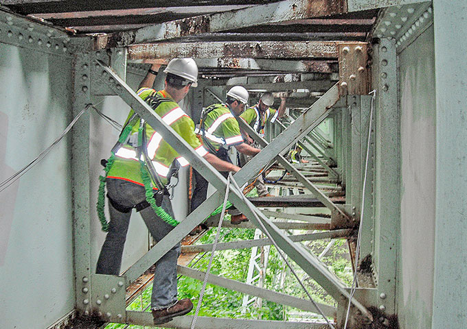
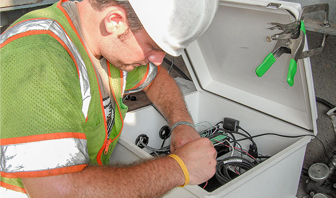
Structural Health Monitoring of SEPTA’s Crum Creek Viaduct
Swarthmore, Pennsylvania, USA
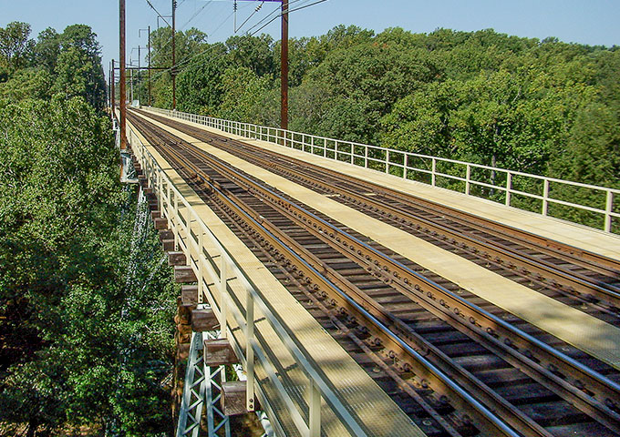
After taking ownership of the Crum Creek Viaduct in early 1980s, Southeastern Pennsylvania Transportation Authority (SEPTA) has repeatedly performed evaluations and assessments on the bridge due to its importance to the regional rail line system. The 900-foot-long Viaduct, constructed in 1897, has 17 spans and a superstructure consisting of four girders carrying two rail tracks, and the substructure consists of steel columns, forming four legged towers. The west tower is a single bent.
Inspection reports had raised concerns about the fatigue life of the superstructure elements, and therefore SEPTA decided to employ advanced sensing and simulation techniques to provide a better understanding of the behavior of the structure, and to propose rehabilitation concepts to improve the performance and lifetime of the bridge.
As part of the preliminary data collection, interpretation and investigation, it was determined that the level of stress in most of the elements were reasonable. After a comprehensive geotechnical investigation was performed on the site and foundations of the structure, it was concluded that slope failure and foundation stability was a concern for this bridge. Therefore, it was recommended to the client that complete geotechnical testing, long-term monitoring, and fatigue analysis may be considered for the next phases of the project.
The rail bridge monitoring system for the Crum Creek viaduct utilized GEOKON Model 4000 Strain Gages to track the change in intrinsic strains over a period of six months in the supporting towers and bents. The objective of the measurements was to determine load distribution between the substructure elements as well as to establish temperature-induced force fluctuations.
For additional information, please visit the Case Summary
-
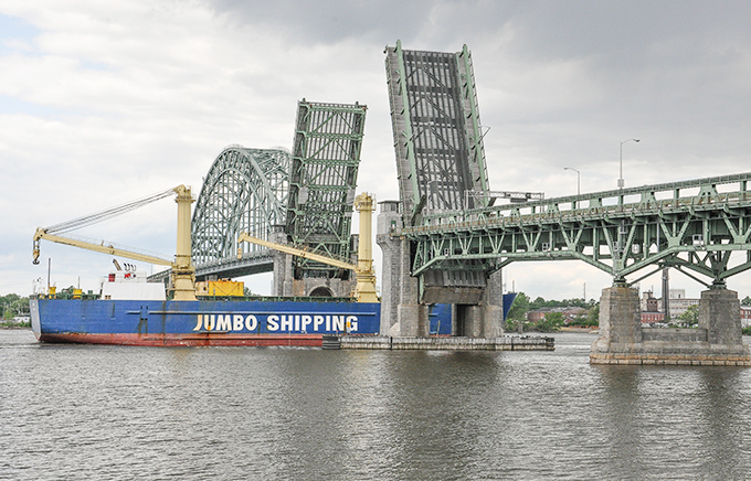
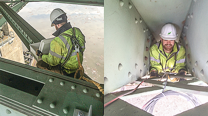
Structural Health Monitoring System for the Tacony-Palmyra Bridge
Tacony, Pennsylvania, USA
Palmyra, New Jersey, USA
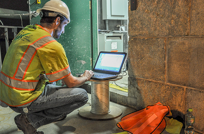
Design and installation of an efficient structural health monitoring (SHM) system capable of providing information regarding the operational and structural performance of the Tacony-Palmyra Bridge. The owner, Burlington County Bridge Commission, has adopted the goal of indefinite preservation for their signature structures and has moved to augment conventional engineering practices with the latest sensing and simulation technology to ensure all decisions are made from the most informed standpoint possible. The Tacony-Palmyra Bridge is a signature long-span bridge that crosses the Delaware River connecting Tacony, Pennsylvania, and Palmyra, New Jersey. The bridge is nearly a mile long and includes a 550-foot steel tied arch span and a 260-foot bascule span.
The SHM system was driven by a comprehensive risk assessment and implemented using the best practices structural identification approach. To date, the primary focus of the system has been placed on addressing operational and maintenance needs and providing quantitative data related to the most critical structural performances.
The SHM system for the Tacony-Palmyra Bridge utilizes a wide variety of sensors and hardware, however GEOKON Model 4000 and Model 4150 vibrating wire strain gages are used to provide measurements on load levels of critical members, seating force of the movable span, and live load force magnitudes. In addition, the expansion and contraction of the 540’ arch is measured with two GEOKON Model 4420 Crackmeters.
For additional information, please visit the Case Summary
-
Monitoring and Evaluating Bridge Expansion Joints with Vibrating Wire Displacement Transducers
Vienna, Austria
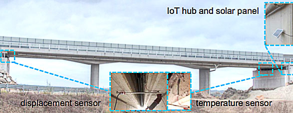
Five Valarm monitoring systems, measuring deformation, temperature and settlement to evaluate the functionality of the expansion joints, were installed on five different bridges along a highway just north of Vienna, Austria.
The monitoring systems use Industrial IoT sensor hubs, designed to collect and transfer measurement data via mobile cell networks to Tools.Valarm.net. The sensor hubs contain modules to read the types of sensors connected, which can include voltage, current, 4-20 mA, 0-10 V, etc. Each sensor hub uses a 5 W solar panel and a 4000 mA battery with a charge controller, which allows the system to remain operational for extended periods of time given the low sampling rate of 1 reading per hour and the hub’s sleep mode between readings. All components fit inside a 30 x 30 x 15 cm enclosure, which is installed at the abutment of each bridge.
GEOKON Vibrating Wire Displacement Transducers are used to monitor the expansion and contraction of the bridge joints with respect to changes in temperature. The transducers’ output is a frequency rather than a voltage, which allows transmission over long (>2000 m) cables without appreciable signal degradation due to variations in cable resistance, which can arise from water penetration, temperature fluctuations, contact resistance or leakage to ground. This, coupled with the rugged transducer design, results in excellent long-term stability and measurements within adverse environmental conditions.
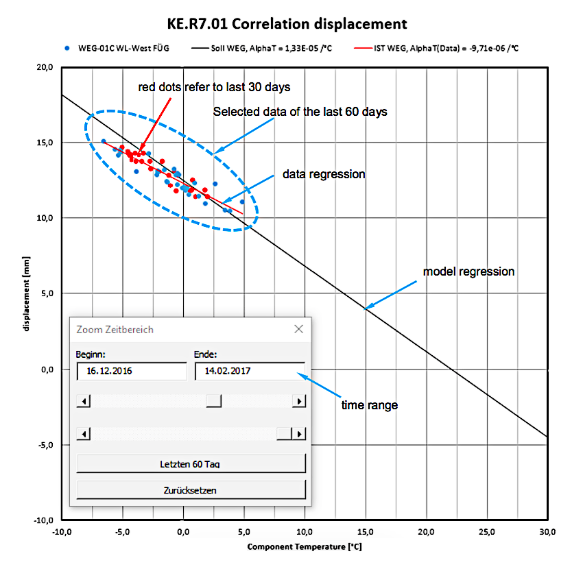
All sensor data is transmitted to the Tools.Valarm.net data visualization platform where it is automatically downloaded and evaluated in an application which cleans the data before processing it to display the correlation between bridge temperature and displacement.
The regression model (top) shows the behavior of the bridge expansion joints over time, which allows the owner to make valid and appropriate conclusions about their performance. This, in turn, helps to determine the most effective maintenance program to insure the structural health and longevity of each bridge.
For additional information, please visit: Valarm web site
-
Jeremiah Morrow Bridge
Ohio, USA
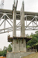
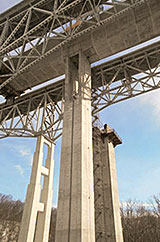
In 2009, the Ohio Department of Transportation initiated the replacement of the twin steel truss Jeremiah Morrow Bridges, located along Interstate 71 between Columbus and Cincinnati Ohio. The new bridges are currently under construction and are post-tensioned cast-in-place segmental concrete box girders on concrete piers, which range from 89 ft to 194 ft in overall height. The longest span of the twin structures is 440 ft with a total length of 2,235 ft, and each bridge has a 52 ft wide roadway carrying 3 lanes of traffic.
Construction control, to ensure correct alignment and corresponding jacking forces, was realized using measurements from a series of vibrating wire tiltmeters, which were mounted on the piers and connected to a data acquisition system. Measurements using traditional laser survey techniques were also incorporated.
For additional information, please contact: Victor Hunt | University of Cincinnati Infrastructure Institute
-
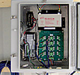
Point Marion Bridge
Pennsylvania, USA
A new bridge is being built 20 m south of the historic Point Marion Bridge, which will be replaced due to its structural deficiencies.
The soft nature of the surrounding foundation soils prompted a geotechnical / structural instrumentation program to monitor the impact of new bridge construction on the aging structure. Automated measurements were taken of 19 Vibrating Wire Piezometers to monitor water pressures in the foundation soils on both sides of the river. In addition, a Vibrating Wire Piezometer was used to record river water levels, and two Vibrating Wire Strain Gages were used to monitor the old bridge. Manual measurements were taken of Tilt Plates, settlement pins (placed in the fill) and Inclinometers installed in the foundation soils.
Data were automatically collected and imported into an MultiLoggerDB database on an hourly basis. MLWeb software was then used to provide the construction contractor and owner with access to data via the Internet.
For additional information, please view the Canary Systems Project Profile
-
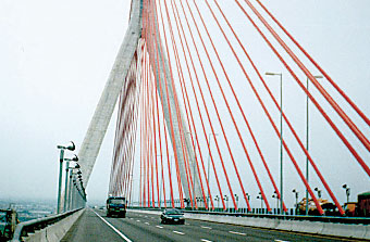
Kao Ping Bridge
South Taiwan
The new Kao Ping Bridge is one of the longest (510 m) and the highest (183.5 m) bridges in Asia. Construction of the bridge began in February 1997 and ended in February 2000. Instrumentation included Strain Gages in the concrete and steel segments.
For additional information, please contact:
-
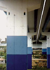
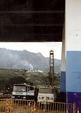
Marbella Relief Road Viaduct
Marbella, Malaga, Spain
In 1997, a landslide occurred in Malaga, Spain, which caused the piers of the Marbella Relief Road Viaduct to tilt. To monitor the ongoing safety of the viaduct, eight vibrating wire Biaxial Tiltmeters were installed at the base of each pier.
For additional information, please contact:
Javier Andreu | Ingeneria de Instrumentacion Y Control
Share your Project!
GEOKON would like to share customer projects and success stories with the visitors of our website. If you would like your project summary to be featured on our Recent Projects page, added to our collection of various Projects and promoted on social media, please complete and submit your project for review and consideration. As a token of our appreciation, GEOKON will send you a small gift for your contribution!
