4.1Adjusting the Gauge Wire Tension
WARNING! Under no circumstances should the gauge tension be adjusted after the gauge has been welded down.
Gauges are supplied with an initial reading of approximately 2500 microstrains. This gives a range of ±1500 microstrains. This range is usually adequate for most purposes and should not be altered except in unusual circumstances.
If the strain directions are known, the wire tension can be adjusted for greater range in either compression or tension by completing the following:
1.Attach the red and black leads to a readout box which has been set to position E.
2.Keep the gauge still by grasping the 4100 gauge by the tube, or the 4150 series gauges by the coil assembly.
3.Using a mini wrench, rotate the tensioning nut. The position of the nut controls the spring tension. To increase the range of measurement to accommodate more compressive strain, turn the nut in a clockwise direction and set the initial reading to between 2500 and 3000 microstrains. To increase the range of measurement for tensile strains rotate the nut in a counterclockwise direction, setting the initial reading to between 1500 and 2000. A rotation of 1/2 turn will give a change of about 600 microstrains. Table 1 details various tension settings.
|
|
Available Microstrain Range |
||
|
Setting Range |
Microstrain Reading |
Tension |
Compression |
|
Midrange |
2500 |
1500 |
1500 |
|
Tension (67% of range) |
2000 |
2000 |
1000 |
|
Compression (67% of range) |
3000 |
1000 |
2000 |
table 1: Guide to Initial Tension Settings
4. The gauge end piece will often turn with the tensioning nut. After the adjustment is made the end piece should be rotated back to its original position so that the flats of the two end pieces are aligned. Again, hold the tube/coil assembly while doing this.
5.Check the reading. If okay, apply a drop of thread locking cement to preserve the nut position and the tension.
4.2Installing the 4100/4150 Via Spot Welding
CAUTION! Wear safety glasses while performing the following tasks.
The surface of the steel member should be flat, clean, and free from rust, grease, and pitting. Degrease the surface using an appropriate cleaning agent, then use a power grinder or sander, file, wire brush or sandpaper, to achieve a flat, smooth surface.
Before welding, it is necessary to test the spot welder to make sure that the correct weld energy is being used. Weld energy, and to a certain extent, contact pressure, determines the quality of the weld. Approximately 20 to 40 watt-seconds of weld energy is required to properly weld 4100 or 4150 strain gauges to structural steel.
Using the test material provided with the gauges, run a series of tests to determine the correct weld energy. When the correct weld energy is used, the test strip will show a series of holes where the welded strip has been left behind on the substrate when peeled back from the steel surface with pliers, as shown below.
10:
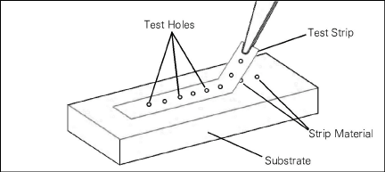
Figure 10: Peel Test
If insufficient weld energy is used, the test strip will pull loose without holes being torn in it. If excessive weld energy is used, the test strip will discolor, melt, and be ejected away from the spot. Sparking is usually an indication of dirt between the test strip and the substrate. It may also be an indication of insufficient force, in which case the force setting of the hand probe should be adjusted. Excessive deformation of the weld area calls for either a decrease of the force applied by the hand probe and/or a decrease of weld energy.
4.2.3Spot Welding the 4100 Gauge
Spot weld one end of the gauge by placing a weld point at each of the marked dots on the mounting tab, in the sequence shown below. Once that is complete, weld the second mounting tab using instructions in Section 4.2.5.
11:

Figure 11: Spot Welding Sequence, Outer Rows
4.2.4Spot Welding the 4150 Gauge
Spot weld the end of the gauge where the cable comes out by placing a weld point at each of the marked dots on the mounting tab in the sequence shown below. Carefully move the lead wires out of the way before beginning.
12:

Figure 12: Spot welding Sequence, Outer Rows
Next, add another row of welds as close to gauge ends as possible, between the welds of the previous row, as shown in below. Once that is complete weld the second mounting tab per the instructions in Section 4.2.5.
13:
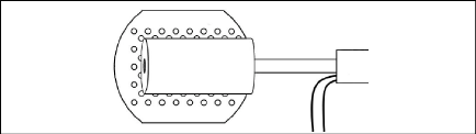
Figure 13: Spot Welding Sequence, Inner Rows
4.2.5Welding the Second End Piece
When all the weld dots on one mounting flange have been welded, proceed to weld the other end as follows:
Place the alignment tool over the two ends of the gauge as shown below. This will ensure that the two ends of the gauge are welded in a straight line.
14:
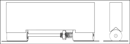
Figure 14: Using the Alignment Tool
With the alignment tool held in place, make a preliminary weld in the center of the second tab, outside of the back row, and close to the outer edge. When this spot has been welded, connect the gauge to the readout box and check the reading.
■If the reading is within the acceptable range, proceed to spot weld two more welds along the back line. Remove the alignment tool and weld the rest of the tab following the same pattern and sequence used for the first tab.
■If the reading is not acceptable, the preliminary weld can be undone by using a sharp razor blade to pry under the tab at a point close to the weld.
Welds should have a slight depression and be uniform in appearance. Keep the hand probe weld-tip clean and free of burrs. Periodically sand it gently with 400-grit sandpaper. Take care to keep the weld-tip a well-rounded point. Proper dressing will keep the tip from sticking to the mounting tab during welding.
Note: When the gauge is used on curved surfaces, make a third row of welds on the periphery of the mounting tab (between the stenciled row and the outside edge).
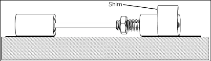
Strain gauge performance is enhanced by the addition of the supplied collar shims. These shims are preformed in the shape of an L, and are welded over the top of the gauge ends as follows:
1.Take the shim and position it over the gauge end so that the edge of the 6 mm (.25") wide shim is flush with the back edge of the end.
2.Use the tip of the welder to press the angle in the collar shim tightly into the corner between the gauge end and the mounting tab as shown below.
15:
16:
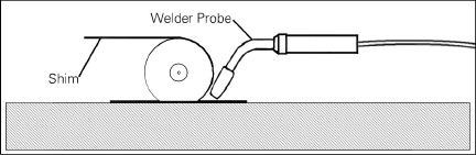
Figure 16: Welding the Collar Shim in Place
3.Weld the bottom end of the collar shim L onto the mounting tab using three welds positioned as close to the corner as possible, and three welds at the outer edge of the collar shim.
4.Bend the collar shim over the gauge end and force it into the corner on the other side of the gauge end using the weld probe as before.
5.Weld it into the corner as before, using a total of six welds.
6.Weld the collar shim to the end block using three welds along the highest point of the gauge end, as shown below.
17:
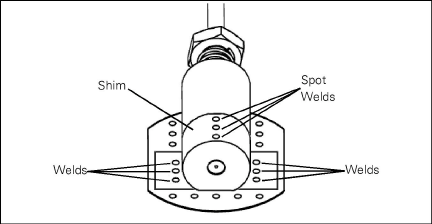
Figure 17: Completed Collar Shim
7.Repeat the process on the other gauge end.
8.When both ends of the gauge have been spot welded, take the handle of a small screwdriver and lightly tap both end blocks at points over the flanges only. The purpose of the tapping is to relieve any local stresses induced by the welding procedure.
9.After tapping four or five times on each gauge end, read the gauge. Continue the tapping procedure until the readings have settled down and are not changing more than a few digits.
All readings are referred to an initial reading; therefore, it is important that this initial reading be taken carefully. It is preferable to install gauges on steel members that are still in an unloaded condition, i.e., prior to their assembly into the structure. In this way, the initial readings correspond to zero load. Otherwise, the initial readings will correspond to some unknown load level.
Record the ambient temperature at the time of each reading, along with notes concerning the construction activity that is taking place. This data might supply logical reasons for observed changes in the readings. For temperature correction factors when used on concrete, see Appendix D.
4.2.7Installing the Plucking Coil Housing (Model 4100 Only)
Remove any masking and place the plucking coil housing over the gauge. Connect the gauge to the readout box and adjust the housing until a steady reading is obtained. In this position, use the spot welder to weld the tabs holding the coiled housing to the substrate.
Next, protect the tabs and surrounding bare metal from corrosion as described in Section 3.4.
4.2.8Installing the Gauge Cover (Model 4150 Only)
geokon provides the 4150 with a semicylindrical metal cover. Spot weld the cover in place over the gauge as shown in the figure below.
Next, waterproof the spot-welding tabs as described in Section 3.4.
18:
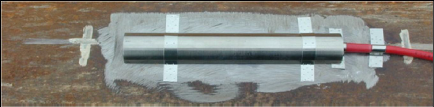
Figure 18: Spot welded Cover Plate
4.2.9Securing the 4150 Gauge Cable
Using the shim stock provided, spot weld the cable to lead wire junction firmly to the steel substrate. Be sure to leave some slack in the lead wires. Using another piece of shim stock, spot weld the cable to the steel substrate, approximately 25 mm (1") behind the lead wire junction.
4.3Installing the 4100/4150 Via Epoxy Bonding
Note: Due to the large number of variables associated with adhesive (thermal cycles, UV exposure, vibration, impact, moisture, corrosion of base steel, etc.), use epoxy cement for short term monitoring only.
Use the following tools and accessories to install the 4100 or 4150 onto steel by epoxy bonding:
■Power grinder or sander, files, wire brush, sandpaper
■Quick-setting two-part adhesive, such as Loctite 410 with accelerator
■Strain gauge setting jig
■Waterproofing compound such as Dow Corning RTV-3145
■Cable ties and/or duct tape (as required)
Do the following to install the gauge:
1.Prepare the surface: Follow the instructions outlined in the spot welding section.
2.Fasten the gauge: Position the gauge in the slot of the setting jig. Apply Loctite 410 to the mounting tabs of the strain gauge. Apply activator to the steel at the approximate locations for the mounting tabs. Press the gauge firmly against the beam and hold for at least 30 seconds, until the Loctite has set.
3.Gauge protection: Apply a layer of waterproofing compound over the mounting tab area.
4.Install the plucking coil housing (for the 4100): Before the waterproofing layer has hardened, install the plucking coil housing over the strain gauge. Don’t use an excessive amount of waterproofing compound. Keep the waterproofing compound away from the gauge tube so that it does not impede the gauge tube's freedom to move relative to the gauge end.
If the plucking coil housing is to be kept portable, squeeze excess waterproofing compound out of the way so that when it sets up it will not prevent the proper seating of the plucking coil housing.
If the plucking coil housing is to be fixed in place permanently, position it over the gauge and look through the transparent housing, moving it until it is clear of the gauge. In this position, fasten it in place using the shim stock provided and procedure described in step 2 above. The area of the substrate to which the tabs are welded will require surface preparation as described in Section 4.2.1. The tabs should be protected from corrosion as described in Section 3.4.
5.Secure the gauge cable: For the 4150, using the shim stock provided, fasten the cable to lead wire junction firmly to the steel. Be sure to leave some slack in the lead wires. Using the second shim stock, fasten the cable to the steel, approximately 25 mm (1") behind the lead wire junction. For the 4100 or 4150, use cable ties or duct tape to secure the gauge cable to the steel member.
6.Fasten the 4150 cover plate: Fill the cover with the waterproofing compound and place it over the gauge. Using the special shim stock strips provided, fasten the strips first to the split tube, and then to the steel member.
All readings are referred to an initial reading; therefore, it is important that these initial readings be taken carefully. Install gauges on steel members that are still in an unloaded condition, i.e., prior to their assembly into the structure. This will ensure that the initial readings correspond to zero load. Otherwise, the initial readings will correspond to some unknown load level.
Record the ambient temperature at the time of each reading, along with notes concerning the construction activity that is taking place. This data might supply logical reasons for observed changes in the readings. For temperature correction factors when used on concrete, see Appendix D.
4.4Installing the 4151 Strain Gauge
Drill two 5 mm (3/16") diameter holes 13 mm (1/2") deep, at a spacing of 51 mm (2"). geokon provides a drill hole spacer bar to make this easier. After drilling the first hole, secure the spacer bar to the hole then use the spacer bar to locate the second hole.
19:
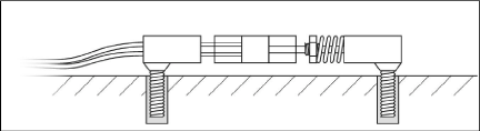
Figure 19: Model 4151 Strain Gauge Installation