geokon recommends the parameters in the table below when using strain gauges with the MICRO-6000 datalogger or any other CR1000 based datalogger. It shows the recommended gauge type selection and gauge factor G entry to convert to microstrain. The table also lists the starting and ending frequency settings for the excitation sweep when writing a program for the CR1000 using the P28 vibrating wire measurement instruction.
Alternately, if a calibration sheet is supplied with the strain gauge, the exact values can be calculated from the start and end frequencies of the calibration.
To maximize the stability and resolution of the sensor, a relatively narrow band of excitation frequency should be selected. Calculate these settings by taking an initial reading and then setting the starting frequency to 200 Hz below and the ending frequency 200 Hz above.
|
MICRO 6000 Gauge Type |
4200 |
|
Gauge Factor G |
Shown on calibration sheet |
|
Start Frequency (P28) |
4 (400 Hz) |
|
End Frequency (P28) |
12 (1200 Hz) |
table 2: Embedment Strain Gauge Datalogger Parameters
5.2Embedment Strain Gauge Readout Positions
The following table indicates the readout position detail for each strain gauge model.
|
Model |
4200/4200HT |
4200 6/7 |
4202 |
4204 |
4210/4212/4214 |
|
Readout Position |
D |
D |
E |
A (Mode: digits) |
B |
|
Display Units |
microstrain (με) |
readout units |
microstrain (με) |
digits (f210-3) |
digits (f210-3) |
|
Frequency Range |
450 1200 Hz |
400-1200 Hz |
1400-3500 Hz |
800-1600 Hz |
1400-3500 Hz |
|
Mid Range Reading |
2500 με |
2000 |
2500 με |
1700 digits |
6000 digits |
|
Minimum Reading |
1000 με |
1000 |
1000 με |
650 digits |
2000 digits |
|
Maximum Reading |
4000 με |
3000 |
4000 με |
2750 digits |
10000 digits |
The following sections describe how to take readings using readout equipment available from geokon.
The Model GK-404 Vibrating Wire Readout is a portable, low-power, hand-held unit that is capable of running for more than 20 hours continuously on two AA batteries. It is designed for the readout of all geokon vibrating wire instruments, and is capable of displaying the reading in either digits, frequency (Hz), period (ms), or microstrain (me). The GK-404 also displays the temperature of the transducer (embedded thermistor) with a resolution of 0.1 °C.
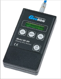
Figure 14: GK-404 Readout
1.Attach the flying leads to the GK-404 by aligning the red circle on the silver Lemo connector with the red line on the top of the GK-404 (see Figure 15 below). Insert the Lemo connector into the GK-404 until it locks into place.
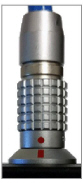
Figure 15: Lemo Connector to GK-404
2.Connect each of the clips on the leads to the matching colors of the sensor conductors, with blue representing the shield (bare).
3.To turn on the GK-404, press the ON/OFF button on the front panel of the unit. The initial startup screen will display.
4.After a delay, the GK-404 will start taking readings and display them based on the settings of the POS and MODE buttons.
The unit display (from left to right) is as follows:
nThe current position: set by the POS button, displayed as A through F.
nThe current reading: set by the MODE button, displayed as a numeric value followed by the unit of measure.
nTemperature reading of the attached instrument in degrees Celsius.
Use the POS and MODE buttons to select the correct position and display units for the model of equipment purchased.
The GK-404 will continue to take measurements and display readings until the unit is turned off, either manually or by the Auto-Off timer (if enabled).
For more information, consult the GK-404 manual.
The GK-405 Vibrating Wire Readout is made up of two components:
nThe Readout Unit, consisting of a Windows Mobile handheld PC running the GK-405 Vibrating Wire Readout application.
nThe GK-405 Remote Module, which is housed in a weather-proof enclosure.
The remote module can be wire-connected to the sensor by means of:
nFlying leads with alligator clips, if the sensor cable terminates in bare wires.
nA 10 pin connector.
The two units communicate wirelessly using Bluetooth®, a reliable digital communications protocol. Using Bluetooth, the unit can operate from the cradle of the remote module, or, if more convenient, can be removed and operated up to 20 meters away from the remote module.
The GK-405 displays the thermistor temperature in degrees Celsius.
For further details, consult the GK-405 Instruction Manual.
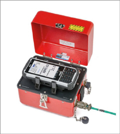
Figure 16: GK-405 Readout
5.4.1Connecting Sensors with 10-Pin Bulkhead Connectors Attached
Align the grooves on the sensor connector (male), with the appropriate connector on the readout (female connector, labeled senor or load cell). Push the connector into place, and then twist the outer ring of the male connector until it locks into place.
5.4.2Connecting Sensors with Bare Leads
Attach the GK-403-2 flying leads to the bare leads of a geokon vibrating wire sensor by connecting each of the clips on the leads to the matching colors of the sensor conductors, with blue representing the shield (bare).
Press the power button on the Readout Unit. After start-up completes, a blue light will begin flashing, signifying that the two components are ready to connect wirelessly. Launch the GK-405 VWRA program by doing the following:
1.Tap Start on the hand-held PC’s main window.
2.Select Programs.
3.Tap the GK-405 VWRA icon.
After a few seconds, the blue light should stop flashing and remain lit. The Live Readings window will display on the hand-held PC.
Set the Display mode to the correct letter required by your equipment. For more information, consult the GK-405 Instruction Manual.
5.5GK-403 Readout Box (Obsolete Model)
The GK-403 can store instrument readings, as well as apply calibration factors to convert readings to engineering units. The GK-403 displays the thermistor temperature in degrees Celsius.
5.5.1Connecting Sensors with 10-Pin Bulkhead Connectors Attached
Align the grooves on the sensor connector (male), with the appropriate connector on the readout (female connector labeled sensor or load cell). Push in the connector, and then twist the outer ring of the male connector until it locks.
5.5.2Connecting Sensors With Bare Leads
Attach the GK-403-2 flying leads to the bare leads of a geokon vibrating wire sensor by connecting each of the clips on the leads to the matching colors of the sensor conductors, with blue representing the shield (bare).
1.Set the display selector to the correct position for your equipment.
2.Power on the unit.
3.A reading will appear in the front display window. (The last digit may change one or two digits while reading.)
4.The thermistor will be read and displayed on the screen above the instrument reading in degrees Celsius.
5.Press the Store button to record the value displayed.
If the no reading displays or the reading is unstable, see Section 5 for troubleshooting suggestions.
The unit will automatically turn off after two minutes to conserve power.
For more information, consult the GK-403 manual.
All geokon vibrating wire transducers are equipped with a thermistor for reading temperature. The thermistor gives a varying resistance output as the temperature changes. The white and green leads of the instrument cable are normally connected to the internal thermistor.
The GK-403, GK-404, and GK-405 readout boxes will read the thermistor and display the temperature in degrees Celsius.
Note: You must use an ohmmeter to read the 4200HT strain gauge.
To read temperatures using an ohmmeter:
1.Connect an ohmmeter to the green and white thermistor leads coming from the equipment. Since the resistance changes with temperature are large, the effect of cable resistance is usually insignificant. For long cables a correction can be applied, equal to approximately 14.7W per 1000 feet (48.5W per km) at 20 °C. Multiply these factors by two to account for both directions.
2.Look up the temperature for the measured resistance in Appendix C. For the 4200HT use Appendix D.