3.Prior To Installation
3.1Adjusting Gauge to the Desired Range
Model 4200 gauges are normally supplied with the wire tension set near the middle of their range. If the range needs to be adjusted for some reason, the wire tension may be changed using the steps below:
1.Attach the red and black leads to a readout box that has been set to position D, reading in microstrain.
2.Grip the small collar under the shrink tube and rotate the end flange as shown in the figure below.
3.Rotate clockwise to decrease the initial reading; rotate counterclockwise to increase the reading. For example, if the gauge will see all compression, it should be set to about 4000 microstrain.
9:

Figure 9: Adjusting the Range of the Strain Gauge
Model 4200-6 / 4200-7 Note: Although the readings are taken on position D, the digits shown must be converted to microstrain manually. To do this, multiply the observed digit change by the gauge factor given on the calibration sheet provided with the strain gauge.
3.1.1Adjusting the Range of Model 4202
Model 4202 gauges are supplied with an initial reading of approximately 2500 microstrain. This gives a range of ±1500 microstrain. This range is usually adequate for most purposes and should not be altered except in unusual circumstances.
If the strain directions are known, the wire tension can be adjusted for greater range in either compression or tension using the steps below:
1.Attach the red and black leads to the readout box pre-set to position E.
2.Grasp the gauge at the center to prevent it from turning in the next step.
10:
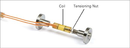
Figure 10: Model 4202 VW Strain Gauge
3.Using a mini-wrench, rotate the tensioning nut. The position of the nut controls the spring tension.
■To accommodate more compressive strain, increase the range of measurement by turning the nut in a clockwise direction to set the initial reading between 2500 and 3000 microstrain.
■To accommodate more tensile strain, increase the range of measurement by turning the nut in a counter-clockwise direction to set the initial reading between 1500 and 2000 microstrain. A rotation of ½ turn will give a change of about 600 microstrain. The following table shows various tension settings.
|
|
Available Strain Range |
||
|
Setting Range |
Strain Reading |
Tension |
Compression |
|
Midrange |
2500 |
1500 |
1500 |
|
Tension (67% of range) |
2000 |
2000 |
1000 |
|
Compression (67% of range) |
3000 |
1000 |
2000 |
table 1: Guide to 4202 Initial Tension Settings
4.The gauge end block will often turn with the tensioning nut. After making the adjustment, grasp the end block and rotate it back to its original position, so that the flats of the two end blocks are aligned. Remember to hold the tube/coil assembly while doing this.
5.Check the reading. If okay, apply a spot of thread locking cement to preserve the nut position and the tension.
Insert the flat part of the gauge into the slot in the coil assembly located at the end of the cable. Slide the hose clamp over the assembly and tighten.
11:
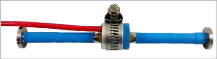
Figure 11: Assembled Gauge and Coil Housing
Alternatively, the coil housing can be glued in place using cyanoacrylate glue. If this method is chosen, it will no longer be possible to remove the gauge from the coil housing.
A preliminary check should be performed before installing the gauge in the field.
To perform the preliminary check, complete the following steps:
1.Using an ohmmeter, check the resistance between the two lead wires (usually red and black).
■For Models 4200, 4200L, 4200-6, 4200-7, and 4210/12/14 it should be about 180 ohms.
■For Model 4202, it should be about 50 ohms.
■Remember to add the cable resistance at approximately 14.7Ω/1000' or 48.5Ω/km at 20 °C. Multiply these factors by two to account for both directions.
2.Using an ohmmeter, check the resistance between the two thermistor wires (usually white and green). Using Table 6, convert the resistance to temperature. Compare the result to the current ambient temperature. (For Model 4200HT see Table 7.)
3.Connect the gauge to a readout box. (See readout instructions, Section 6.) Observe the displayed readout. The reading should be about the midrange position as defined in Table 2.
4.Press on the gauge ends and confirm that it makes the reading decrease.
Return any faulty gauges to the factory. Gauges should not be opened in the field.