The table below shows the readout position, theoretical gauge factors, and experimental data derived from batch calibrations for each model of strain gauge. (Individual calibrations are available at an additional cost; contact geokon for more information.)
|
Model |
Readout Position |
Theoretical Gauge Factor |
Typical Batch Factor1 |
Typical Gauge Factor1 |
Experimental Data |
|
4200/4200L/4200HT |
D |
3.304 |
0.97 to 0.98 |
N/A |
3.237 |
|
4200 6 |
D |
N/A |
N/A |
N/A |
None |
|
4200 7 |
D |
N/A |
N/A |
N/A |
None |
|
4202 |
E |
0.391 |
0.91 |
N/A |
0.356 |
|
4204/4204L |
A |
N/A |
N/A |
1.422 |
N/A |
|
4210 |
B |
N/A |
N/A |
0.3568 |
0.3423 |
|
4212 |
B |
N/A |
N/A |
0.3624 |
N/A |
|
4214 |
B |
N/A |
N/A |
0.3665 |
N/A |
|
1 The exact Gauge Factor is determined by actual calibration, there is no Batch Factor to apply. |
|||||
table 3: Embedment Strain Gauge Factors
Use position A for the following models:
■Model 4204
■GK-404 (select digits mode)
■GK-403 and GK-405 (convert the period to digits using this formula:)

equation 1: Period to Digits Conversion
For gauges read in position B, gauge factors must be applied to the change in readings. These gauge factors are either average gauge factors for that batch of gauges, or gauge factors from individual calibrations.
7.3Readout Box Positions D & E
Reading for Models 4200 (position D) and 4202 (position E) are displayed on the readout box directly in microstrain based on the theoretical equation:
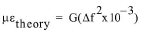
equation 2: Theoretical Strain
Where:
f is the frequency in digits.
G is the theoretical gauge factor, equal to 3.304 for the 4200 gauge and 0.3910 for the 4202 gauge.
In practice, the act of clamping shortens the vibrating wire slightly, causing it to over-register the strain. You can compensate for this by applying the batch gauge factor supplied with each gauge. With the batch gauge factor applied, the apparent change in strain shown on the readout box is equal to:
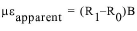
Where:
R0 is the initial reading
R1 is the current reading from the readout box, taken in position D or E.
Note: When (R1 - R0) is positive, the strain is tensile.
B is the batch gauge factor suppled with each gauge.
Temperature variations of considerable magnitude are not uncommon, particularly during concrete curing; therefore, it is always advisable to measure temperatures along with the measurement of strain.
Temperature-induced expansions and contractions can give rise to real changes in the stress of the concrete if the concrete is restrained in any way. These stresses are superimposed on any other load-related stresses.
Temperature can also affect the strain gauge. Increasing temperatures will cause the vibrating wire to elongate and thus go slack, indicating what would appear to be a compressive strain in the concrete. This effect is balanced to some degree by a corresponding stretching of the wire, caused by expansion of the concrete. If the concrete expanded by exactly the same amount as the wire, the wire tension would remain constant, and no correction would be necessary.
However, the steel expansion coefficient is different from the concrete expansion coefficient. Due to this difference, a temperature correction is required equal to:
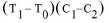
equation 4: Correction for Temperature Effects on the Gauge
Where:
T0 is the initial temperature.
T1 is the current temperature.
C1 is the coefficient expansion of steel: 12.2 microstrain/°C.
(C1 for Model 4200HT gauges is 17.3 microstrain/°C.)
C2 is the coefficient of expansion of concrete: ~10 microstrain/°C. (Users should use their own values for C2 if known.)
Load-related strain in concrete (a composite of both external load and temperature effects) corrected for temperature, is given by:

equation 5: True, Load-Related Strain Corrected for Temperature
Where:
R0 is the initial reading.
R1 is the current reading from the readout box, taken in position D or E.
Note: When (R1 - R0) is positive, the strain is tensile.
B is the batch gauge factor suppled with each gauge.
T0, T1, C1, and C2 are the same values as shown in Equation 4.
A theoretical example of the above is shown below.
Example:
If:
R0 = 3000 in position D
R1 = 2900 in position D
T0 = 20 °C
T1 = 30 °C
B = 0.975 (batch calibration factor)
Then:
The apparent strain = (2900 – 3000) 0.975 = –97.5 mstrain (compression).
The load-related strain, corrected for temperature effects on the gauge = (2900 – 3000) 0.975 + (30 – 20) (12.2 – 10) = –75.5 mstrain (compression).
Note: The actual strain undergone by the concrete, (i.e., that which would be measured by a measuring scale) is given by the formula:
μactual = (R1 – R0) B + (T1 – T0) (C1)
Which in the current example = (2900 – 3000) 0.975 + (30 – 20) (12.2) = 24.5 mstrain (expansion).
See Appendix G for further information.
7.4.1Model 4200-6 / 4200-7 Corrections
The effect of temperature on the 4200-6 and 4200-7 strain gauges is complex; it varies depending on the strain level. A typical temperature correction factor to be applied to the 10,000 με 4200-7 model is as follows:
Temperature Correction Factor = (0.000401*R1 - 1.067)(T1-T0)
Where:
R1 is the current gauge reading.
T1 is the current temperature in degrees Celsius.
T0 is the initial temperature in degrees Celsius.
This correction factor was developed by testing four gauges at three different parts of their range (i.e., at microstrain levels of 4000, 8000, and 12000), at five different temperature levels, i.e., -40, -20, 0, 20, 40, and 60 degrees Celsius).
When using the polynomial expression to calculate the strain, this correction factor must be applied to the current reading R1. The modified value of R1 is then inserted into the polynomial.
Thus, the modified value of R1 to be inserted into the polynomial is:
R1+ (0.000401*R1 – 1.067) x (T1 - T0)
A well-known property of concrete is its propensity to shrink as the water content diminishes, and to swell as it absorbs water. This shrinkage and swelling can give rise to large strain changes that are not related to load or stress. The magnitude of these strains can be several hundred microstrain.
It is difficult to compensate for these unwanted strains. An attempt may be made to keep the concrete under a constant condition of water content, but this is frequently impossible on concrete structures exposed to varying weather conditions. The shrinkage and/or swelling effect may be measured by casting a strain gauge inside a concrete block that remains unloaded, yet still exposed to the same moisture conditions as the active gauges. Strains measured on this gauge may be used as a correction factor.
It is also well-known that concrete will creep under a sustained load. What may seem to be a gradually increasing load, as evidenced by a gradually-increasing strain, may actually be strain due to the concrete creeping under a constant, sustained load.
On some projects, gauges have been cast into concrete blocks in the laboratory and kept loaded by means of springs inside a load frame. In this manner, the creep phenomenon can be quantified.
7.7Effect of Autogenous Growth
Some older concretes that have a particular combination of aggregates and alkaline cements may expand with time as they undergo a chemical change and recrystallization. This is called autogenous growth and is like creep, but in the opposite direction, and is difficult to quantify.
The load in any structural element to which the strain gauge is attached is given by the formula:

equation 7: Strain to Load Formula
Where:
L is the load.
E is the elastic modulus of the structural element in the appropriate units.
µ is the strain in microstrain.
A is the cross-sectional area in the appropriate units.
When installing strain gauges in concrete piles it is standard practice to install them in pairs on either side of the neutral axis. This allows any strains imposed by bending to be corrected by taking the average strain of the two gauges. It is also standard practice to install a pair of strain gauges close to the top of the pile. The measured strain of these two gauges is used to calculate the modulus of the concrete.
For some concrete strain measurements during the early stages of curing it is important to know the effective modulus of the strain gauge. The effective modulus of the various embedment gauges is shown in the following table:
|
Model |
E, approximate |
|
4200 |
596,000 psi |
|
4200L |
56,500 psi |
|
4200-6 / 4200-7 |
N/A |
|
4200HT |
596,000 psi |
|
4200HT-T |
11,950,000 psi |
|
4202 |
610,000 psi |
|
4204 |
596,000 psi |
|
4204L |
56,500 psi |
|
4210 / 4212 / 4214 |
2,350,000 psi |