1.Splicing Prep
The geokon Model 4500-9-HDF1 and 4500-9-HDF2 Armored Cable Splice Kits are designed to enabling splicing armored cables both to other armored cables and to unarmored cables. See the figures below.
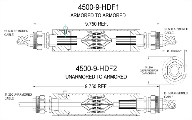
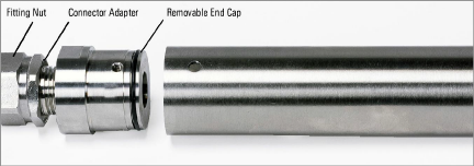
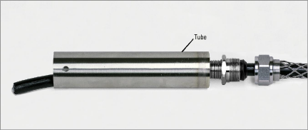
figure 1: Model 4500-9-HDF1 and -HDF2 Cutaway View
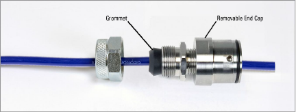
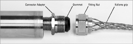
One end of the splice tube features a removable end cap, allowing access to the inside of the tube. The other end of the tube is fixed. Both tube ends feature removable fitting nuts, designed to accept cables of multiple sizes. See the figure below.
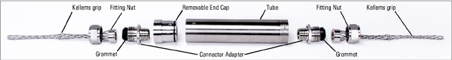
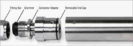
figure 2: Model 4500-9-HDF1 Disassembled View
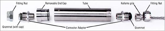
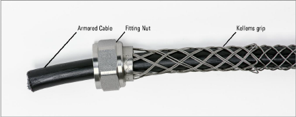
figure 3: Model 4500-9-HDF2 Disassembled View
The general procedure for making the splice is as follows:
1.Position the cables appropriately, through both ends of the splice tube.
2.Splice the wire leads together.
3.Reassemble the end components.
4.Reconnect the fixed end to the tube body, leaving the removable end cap assembled but unattached.
5.Prepare and pour the encapsulant into the tube body, fixed end down.
6.Reconnect the removable end cap to the tube body.
7.Wait for the encapsulant to cure.
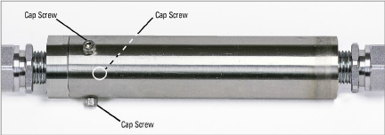
1.Remove the three #10-32 x 3/8” long hex socket head cap screws from the circumference of the tube.
2.Detach the removable end cap from the tube.
3.Unscrew and remove the cable fitting nut from the removable end cap.
Note: For preparing blue unarmored cable, please refer to Section 1.1.2.
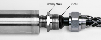
1.Slide the black 02-500PEI armored cable through outer end of the Kellems grip and and through the fitting nut.
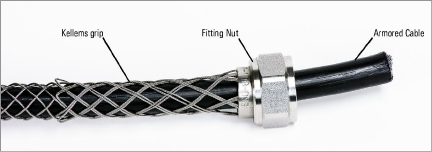
Note: Compress the Kellems grip lengthwise to aid in sliding the cable.
2.Slide the cable through the black grommet, and then through the end cap.
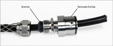
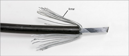
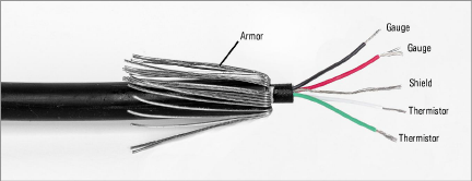
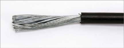
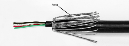
3.Strip the cable’s black outer jacket back approximately 1 ½" (40mm) from the end to expose the armor and wire leads.
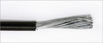
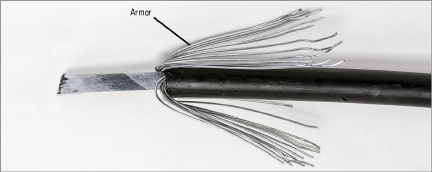
4.Bend the exposed armor backward over the outer jacket.
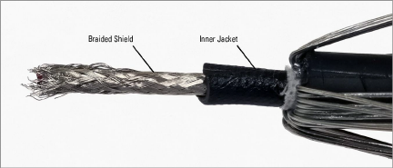
5.Remove the paper and 25 mm (1 inch) of inner jacket to expose the braided shield.
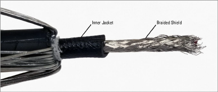
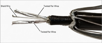
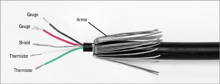
6.Remove the braided shield to expose the two twisted pair wires and shield wire.
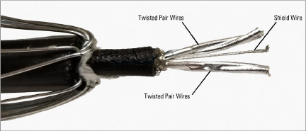
7.Remove the mylar wrapping to expose the 2 pair wire leads and shield wire.
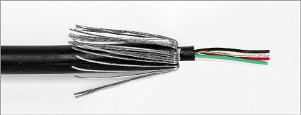
8.Strip the insulation back approximately 12 mm (½ inch) on the red & black gauge wires and on the green & white thermistor wires.
Note: Do not connect the fitting nut to the connector adapter until you after you have finished splicing the wire leads. Refer to Section 2 for more information.
For instructions on making the splice, see Section 2.
For preparing black armored cable, please refer to Section 1.1.1.
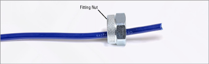
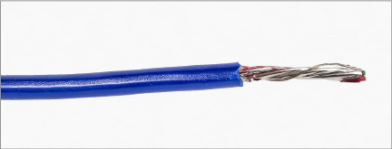
1.Slide the blue 02-250V6 unarmored cable through outer end of the Kellems grip and and through the fitting nut.
2.Slide the blue cable through the black grommet and end cap.
3.Strip the cable’s blue outer jacket back approximately 40 mm (1 ½ inches) from the end to expose the mylar-coated twisted-pair of wire leads.
4.Unwind the leads to separate the pair and the shield wire.
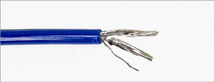
5.Remove the mylar wrapping to expose the wire leads.
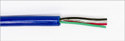
6.Strip the insulation back approximately 12 mm (½ inch) on the red & black gauge wires and on the green & white thermistor wires.
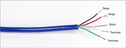
Note: Do not connect the fitting nut to the connector adapter until you after you have finished splicing the wire leads. Refer to Section 2 for more information.
For instructions on making the splice, see Section 2.
1.Unscrew and remove the cable fitting nut from the fixed end of the tube.
2.Slide the black 02-500PEI armored cable through outer end of the Kellems grip and and through the fitting nut.
Note: Compress the Kellems grip lengthwise to aid in sliding the cable.
3.Slide the cable through the black grommet, and then through the connector adapter.
4.Continue to slide the cable through the tube until it protrudes from the end.
5.Strip the cable’s black outer jacket back approximately 40 mm (1.5 inches) from the end to expose the armor and wire leads.
6.Bend the exposed armor backward over the outer jacket.
7.Remove the paper and 25 mm (1 inch) of inner jacket to expose the braided shield.
8.Remove the braided shield to expose the two twisted pair wires and shield wire.
9.Remove the mylar wrapping to expose the 2 pair wire leads and shield wire.
10.Strip the insulation back approximately 12 mm (½ inch) on the red & black gauge wires and on the green & white thermistor wires.
Note: Do not connect the fitting nut to the connector adapter until you after you have finished splicing the wire leads. Refer to Section 2 for more information.