2.Installation
1:

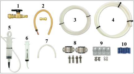
Figure 1: Model 4655 Accessories
The items shown in the figure above are as follows:
1.Bi-directional valve
2.Rubber tubing and union for vacuum pump attachment
3.¼" polyethylene, vent line tubing
4.½" nylon, liquid line tubing
5.Syringe for making small adjusting in the level of fluid in the reservoir through the Swagelok in the cap
6.Syringe for extracting air or liquid from the sensor through the seal screw hole
7.Jumper line for connecting the settlement system liquid reservoir to the desiccant chamber
8.Sensor mounting brackets and suppled hardware
9.Reservoir enclosure mounting feet and supplied hardware
10.Spare desiccant packs
2.2Installing the Reservoir and Sensors
The first step is to determine the elevation of all the sensors and the reservoir. Remember that the reservoir should be above every sensor and that the difference in elevation between the reservoir and any sensor should be within the full-scale range of the pressure transducers. The reservoir should be attached to a stable structure or one that can be easily level surveyed.
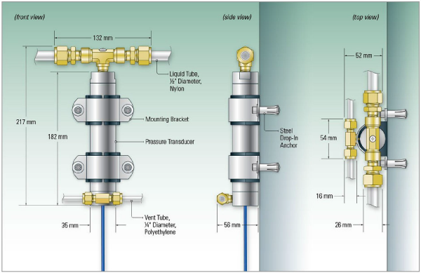
The sensors are installed by attaching the supplied brackets to the concrete or other surface using either the supplied drop-in style anchor, or bolts/studs that are welded to or screwed into the steel or other material as shown in Figure 2.
Mounting Sensors to Cement with the Provided Drop-in Anchors
1.Use a leveling device to align the first mounting bracket vertically on the wall. Mark the locations where the two anchors will be installed.
2.Using a masonry drill (or other suitable equipment), drill two 12 mm (½") holes approximately 37 mm (1.5") deep. Clean the holes thoroughly, blowing out with compressed air if possible.
3.Insert the expansion anchors into the holes. (The threaded end should be closest to the opening.)
4.Insert the provided setting tool, small end first, into an anchor. Expand the anchor by hitting the large end of the setting tool with several sharp hammer blows. Repeat for the second anchor.
5.Repeat steps one through four for the second mounting bracket.
6.Attach the sensor to the wall using the mounting brackets and supplied hardware, as illustrated in the figure below.

Figure 2: Model 4655 Mounting Details
The tubing should be installed after the sensors and reservoir have been fixed in position.
Note: Fluctuating temperatures can change the specific gravity of the fluid, which can be difficult to correct. To avoid this problem, be sure to shield the tubing from direct sunlight.
Tee connectors are supplied for both the liquid and air lines; the reservoirs are delivered with both tubing connectors and caps, depending on whether the system is a series system, a "branch" system, or a combination of the two.
Only nylon tubing should be used for the liquid line because it is the best material for keeping air out of the system thereby preventing the formation of bubbles in the liquid lines (which would adversely affect the readings). The liquid tubing runs should be as straight as possible, ideally within an elevation of ±9.5 mm (0.375"), without rises and dips. (Some minor dips in the line are allowable if using a vacuum to fill.) Siphons must be avoided at all cost. The minimum recommended bend radius for the liquid tubing is 31.8 mm (1.25").
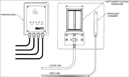
The routing of the vent line is much less critical than the routing of the liquid line. It may be run along any path, so long as it is installed below the liquid line. See Figure 3.) One end of the vent line is capped off at the tee fitting of the most remote sensor, while the other end terminates at a desiccant chamber located next to the reservoir.

Figure 3: Model 4655-1 Reservoir, Desiccant Chamber, and Terminal Box
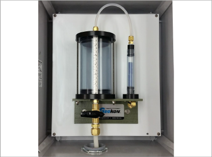
Use the provided jumper line to connect the settlement system liquid reservoir to the desiccant chamber. Depending on site conditions, adding or removing the jumper may help to stabilize the sensor readings.
4:

Figure 4: Liquid Reservoir and Desiccant Chamber connected with Jumper