A valuable feature of the Model 4660 settlement system is the ability to perform in situ calibrations. Do this by connecting an auxiliary reservoir to one of the fluid lines, as shown in the figure below.
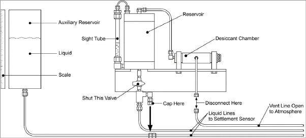
Figure 12: In Situ Calibration Apparatus
First close off the valve at the bottom of the reservoir, half-fill the auxiliary reservoir with the same liquid used in the reservoir and connect it via a short length of tubing to one of the fluid lines, being careful not to introduce air into the lines. Cap off the open fitting on the reservoir connection and disconnect the vent line from the vent manifold. Raise and lower the auxiliary reservoir by measured amounts using a scale to measure the elevation of the water level.
Read the sensor using a GK-404 or GK-405 readout box. (See Section 3 for readout instructions.) Record the readings after allowing sufficient time for the readings to stabilize (usually requires around one to five minutes although it will be noted that the sensor responds instantaneously to change of water elevation even where the liquid tubes are very long.) Record the sensor readings at five or more different elevations, then, from the data calculate the calibration factor and compare it with the factory generated value on the calibration report.
Remove the auxiliary reservoir and reconnect the fluid line to the base of the reservoir and the vent line to the desiccant chamber or vent line manifold. Reopen the valve at the base of the reservoir.
This procedure is not recommended as a regular procedure but only one to be undertaken if there is some serious doubt as to the zero stability of the sensor or to confirm a sudden or critical change in the amount of settlement which is causing concern.
Disconnect the vent line from the desiccant chamber. Close the valve at the bottom of the reservoir. Disconnect the liquid lines from the bottom of the reservoir connect one of them to a nitrogen cylinder. Turn on the nitrogen and adjust the pressure so that the sensor reading is at its maximum value. (Do not exceed 20% above this maximum range.) The other tube can be left open (with long lengths of tubing (>200 m) the process can be speed up by attaching a vacuum pump to the end of the other fluid line.) Once all the liquid has been purged from the lines, allow the nitrogen to flow for another 30 minutes. This will tend to dry out the inside of the tubing. Turn off the nitrogen and disconnect the ends of the tubing so that they are both open to atmosphere along with the open vent line. Wait until the sensor reading stabilizes and then record this zero reading. Compare this reading with the factory zero reading shown on the calibration chart.
Refill the liquid lines following the flushing procedures described in Section 5.2 with the following difference: If a vacuum pump is used, allow the vacuum pump to run for 30 minutes (or until the sensor reading has stabilized), before opening the valve at the bottom of the filling tank to allow liquid to enter the lines. This will greatly reduce the chances of air being trapped inside the tubing and sensor cavities.