A network must include a gateway and at least one logger that is within radio range of the gateway.
|
|
geokon recommends that you configure your network with the devices at the same location, in close proximity to each other, before you deploy them to their respective on-site positions. Skipping or omitting steps, or performing them out of order, could complicate the installation of your network. An installation tutorial on the geokon website, https://www.geokon.com/tutorial-videos, can help with this. |
Install the network using the following steps:
1.Configure the Network
■Prepare the Gateway and Loggers
■Configure the Gateway
■Activate the network
2.Deploy the network
■Mount the devices
■Connect the Loggers to the sensors.
■Link the Cellular Gateway to the Cloud (if used)
Configure the Network
3.1Prepare the Gateway and Loggers
3.1.1Install the Antennas on all Devices
Remove the rubber caps from the antenna mounts. Position the antennas on the mounts and then rotate the antennas in a clockwise direction until tightened.
3.1.2Remove the Covers from all Devices
Remove the cover by unscrewing the four captive screws on the front of the enclosure. Ensure that no dirt, water, or other contaminants are allowed to enter the enclosure.
Repeat this for each device.
3.1.3Configure the Channel on all Devices
geokon configures all devices to use Channel 1; if no other networks operate in the area, then no specific network configuration is needed and you can skip to Section 3.2.
If multiple networks are within radio range of each other, then each network (up to a limit of 12) must be configured to use a different channel. Devices of each network must be set to their respective channel.
Set the Gateway and Logger channel:
Move the channel select DIP switches (shown in the figure below) to any of the twelve valid positions listed in Table 4 below. The setting will take effect at power-up, or after the device is reset.
13:
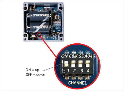
Figure 13: Channel Select Switches
|
1 |
2 |
3 |
4 |
|
|
1 |
OFF (down) |
OFF |
OFF |
OFF |
|
2 |
ON (up) |
OFF |
OFF |
OFF |
|
3 |
OFF |
ON |
OFF |
OFF |
|
4 |
ON |
ON |
OFF |
OFF |
|
5 |
OFF |
OFF |
ON |
OFF |
|
6 |
ON |
OFF |
ON |
OFF |
|
7 |
OFF |
ON |
ON |
OFF |
|
8 |
ON |
ON |
ON |
OFF |
|
9 |
OFF |
OFF |
OFF |
ON |
|
10 |
ON |
OFF |
OFF |
ON |
|
11 |
OFF |
ON |
OFF |
ON |
|
12 |
ON |
ON |
OFF |
ON |
In a new network, be sure to power the gateway before powering the loggers.
When the unit is powered, a green LED on the right side of the box will flash twice after a small delay, indicating the unit has power. The LEDs will not flash again until at least one logger has joined the Network.
Note: Deployment mode starts as soon as devices are powered on or reset. See Section 3.7 for information on Deployment mode.
Note: If replacing batteries in an existing network, ensure that the network is in Deployment Mode prior to removing the batteries. See Section 4.3 for more information on battery replacement.
■Cellular Gateway 890X-XX-LTM-USB, 890X-XX-03G-USB
Move the battery switch to the EXT BATTERY or INT BATTERY position, according to the chart below. Connect to external DC power, then proceed to Section 3.2.3.
For solar panel information, see Appendix F.
|
|
Geographic Zone |
|
|
Power Source |
Sub Polar |
Temperate |
|
Mains or solar with external battery |
EXT BATTERY |
INT BATTERY |
|
Solar without external battery |
N/A |
|
table 5: Cellular Gateway Battery Switch Options
14:
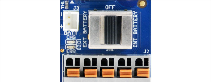
Figure 14: Cellular Gateway Battery Switch
■ Local Gateway 890X-XX-SUP-232, 890X-XX-SUP-USB
Move the battery select switch to either the ALKALINE or LITHIUM position depending on the type of battery being used.
Align the positive (+) side of the batteries with the + indicator in the battery holder. Push the batteries straight down into the holder.
15:
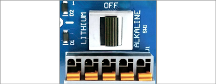
Figure 15: Local Gateway Battery Switch
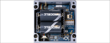
Figure 16: Battery Switch Location Detail
1.Place the supplied desiccant packs inside the enclosure.
2.Ensure the cover gasket and the mating ridge on the enclosure are clean, and that the gasket is properly seated inside the groove on the cover. Place the cover on the unit.
3.Tighten the cover screws slowly. If an electric screwdriver is used, do not fully tighten the screws; do the final tightening by hand. Work in a diagonal pattern.
Important! Make sure the cover seals tightly and evenly.
A Cellular Gateway will set the network time automatically when it connects to the cellular network. A Local Gateway must have its time set manually using geokon’s "Agent" data collection software.
Connect the Local Gateway to the computer using the geokon-supplied USB cable. For RS-232 models, connect the USB cable using the geokon-supplied RS-232 adapter.
Note: For details on setting up a Network in Agent, watch the Agent software tutorial or refer to the Agent instruction manual. The network will not begin collecting data until the network time is set.
Press the Status button to verify that the network time is set. The LEDs should flash both green and red. If only the red LED flashes:
■For a Cellular Gateway, wait several minutes and try again.
■For Local Gateway, set the network time using Agent.
3.2.6Record the Gateway Serial Number
The serial number of the gateway is required when using Agent software and when commissioning the gateway.
Power the loggers in a manner similar to the process of powering the gateway. Do the following:
1.Move the battery select switch to either the ALKALINE or LITHIUM position depending on the type of battery being used.
2.Align the positive (+) side of batteries with the + indicator in the battery holder. Push the batteries down into the holder.
An LED will flash twice, indicating the unit has power.
3.3.2Verify the Network Connection of the Loggers
If the gateway is in Deployment mode, the loggers will join the network about 30 seconds after power up, as indicated by the LED(s) on the loggers flashing in unison with the gateway.
Verify that the LED indicators on the loggers and the gateway are flashing green only. This may take several minutes depending on network configuration.
The attached mounting bracket is designed to be used with U-bolts, hose clamps, screws, etc. Mount all devices vertically, with the antenna pointing up.
geokon recommends a mounting height of at least two meters. Lower than two meters may compromise performance; as a rule, higher is usually better.
3.4.1Mounting Location Considerations
Select the mounting location with care. Certain mounting configurations can hinder or even completely block wireless signal transmission, or can introduce electrical noise to the signal.
Common mounting mistakes include the following:
17:
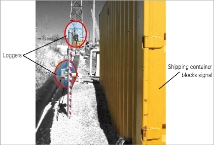
Figure 17: Installing Near a Large Object
18:
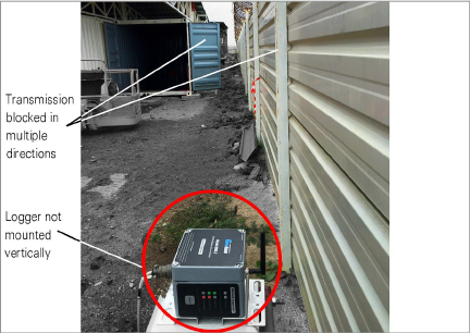
Figure 18: Installing Close to Buildings or Fences/Walls, and/or Horizontally
19:
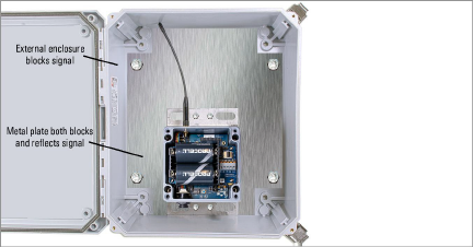
Figure 19: Mounting onto a Metal Plate and/or Inside an Enclosure
Large structures, such as walls, buildings, hills, etc. can block and/or reflect RF signals. Tips include:
■Mount antennas above metallic structures.
■Keep in mind that loggers communicate with each other, not just with the gateway.
■A high Received Signal Strength Indicator (RSSI) level does not guarantee trouble-free communication.
■Mount devices such that their antennas are on top, pointing upward.
3.4.2Ground the Gateway and Loggers
Install a grounding rod and cable, or other suitable ground, at a location near each device. Cellular Gateways and multiple-channel loggers come equipped with a copper grounding lug to which you can connect the grounding cable. Ground Local Gateways and loggers by connecting the grounding cable to the mounting bracket.
3.5Connect the Sensors to Loggers
3.5.1Making Cable Gland Connections
To connect a device using a cable gland connection:
1.Loosen the nut on the cable fitting and remove the white plastic dowel.
2.Slide the transducer cable through the cable gland nut and fitting.
3.Insert the lead wires into the terminal block as shown in Figure 20 and Table 6. Press down on the orange tab, insert the bare end of the wire into the terminal block, and then release the tab.
4.Pull gently on each conductor to ensure it is secure.
5.Tighten the cable gland nut until it firmly grips the outer jacket of the cable. The cable gland nut must be properly tightened to prevent water entry. Do not over-tighten, as this might strip the plastic threads.
6.Pull gently on the gauge cable to ensure it is held in place by the cable gland.
7.Repeat these steps for each gauge cable to be connected.
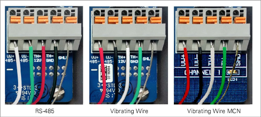
Figure 20: Terminal Connections
To prevent a short circuit, do not allow bare leads to touch each other during or after wiring.
|
RS-485 (Mesh Addressable Logger) |
|
Single/Multiple‑Channel Mesh VW Logger |
||||
|
Position |
Color |
Description |
|
Position |
Color |
Description |
|
485+ |
WHITE |
RS-485 Data + |
|
VW+ |
RED |
Vibrating Wire + |
|
485− |
GREEN |
RS-485 Data − |
|
VW− |
BLACK |
Vibrating Wire − |
|
12V |
RED |
12 Volt Bus |
|
TH+ |
WHITE |
Thermistor + |
|
GND |
BLACK |
Bus Ground |
|
TH− |
GREEN |
Thermistor − |
|
SHD |
BARE |
Analog Ground (shield) |
|
SHD |
BARE |
Analog Ground (shield) |
3.5.2Making 10-Pin Cable Connections
To connect a device using a 10-pin connection:
1.Remove the cover from the 10-pin connector.
2.Align the grooves on the sensor connector (male), with the connector on the logger (female).
3.Push the connector into place and then twist the outer ring of the male connector until it locks.
3.5.3Notes about Multiple-Channel and Addressable Loggers
■For ease of wiring, sensor cables should be inserted into the cable glands on multiple-channel loggers from left to right.
■Sensors should be wired into the channels of a logger in sequence starting with Channel 1.
■Do not wire sensors into the terminal blocks marked '485 IN' and '485 OUT' on a multiple-channel logger.
■Multiple-channel loggers and addressable loggers stop trying to read an empty channel after two attempts. The logger will read all channels at the top of every hour; it will resume sampling when it detects a sensor.
Seal the loggers using the instructions in Section 3.2.3.
Important! Make sure the cover seals tightly and evenly.
WARNING: Single-channel enclosure lids are square but not symmetrical. They must be oriented correctly; attempting to seal a misaligned lid could strip the threads and/or allow moisture to enter the enclosure.
3.5.5Record Logger and Sensor Serial Numbers
Record the serial numbers of both the loggers and of the attached sensors.
For multiple-channel loggers, also record the channel to which each sensor has been connected.
The serial numbers are required when using Agent software and when commissioning the Cellular Gateway.
3.6Cellular Gateway Commissioning
Commissioning allows the Cellular Gateway to account for all of the loggers in the network. For ease of setup, make sure all loggers have been added to the network before commissioning the gateway.
Note: The Cellular Gateway cannot account for loggers added to the network after the commissioning process has been completed. Run the commissioning process again when adding new loggers.
To commission the Cellular Gateway, do the following:
1.Display https://api.geokon.com in a Web browser.
21:
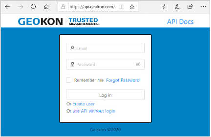
Figure 21: Accessing the Cloud
2.Click "create user".
Note: To access your data using an API, click "use API without login".
3.Enter your credentials and read/agree to the terms of service.
22:
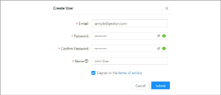
Figure 22: Create a User
4.Click Submit.
5.Log in using your email address and password.
6.Click "Add account".
23:
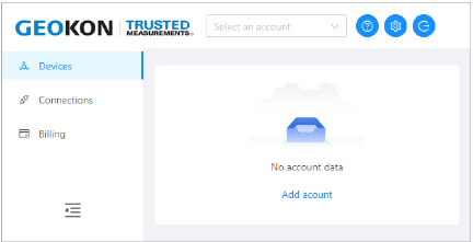
Figure 23: Add an Account
7.Click "create new account".
24:
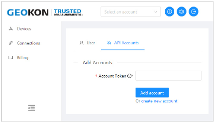
Figure 24: API Accounts
8.Enter your credentials and credit card information, then click Submit. A copy of the account token will be emailed to the address associated with the account as a receipt.
25:
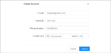
Figure 25: Enter your Credentials
9.Click Devices, then enter the serial number of the Cellular Gateway.
26:
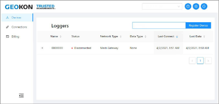
Figure 26: Enter the Serial Number
10.Click Register Device.
11.Click the button next to Activate Cellular Service to activate the Cellular Gateway.
27:
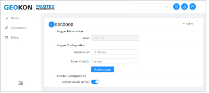
Figure 27: Activate Cellular Service
12.Add logger(s) to the gateway by clicking the + sign next to the Cellular Gateway name. Populate the fields that display.
13.Add sensors to the logger(s) by clicking the + sign next to a logger, then enter the serial number(s) of the sensor(s) attached to the logger, one per channel.
28:
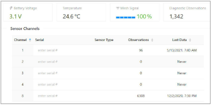
Figure 28: Enter Sensor Serial Numbers
14.Click Update Info to save the sensor configuration.
29:
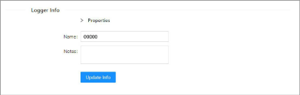
Figure 29: Update the Sensor Configuration
15.Repeat steps 12 – 14 for all loggers on the Network.
16.Click Connections, then enter a token name in the Create Token field.
17.Click Create Token. A new token entry displays.
18.Click the blue token to copy it to the Windows Clipboard.
30:
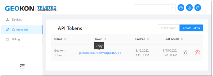
Figure 30: Copy the Token
19.Paste the token into geokon’s data collection software, "Agent", to commission the Cellular Gateway and retrieve data.
There are two modes of operation: Deployment mode and Normal mode. Deployment mode allows loggers to be quickly added to a network and verified.
Put the gateway into Deployment mode before making any changes, such as adding loggers (during initial setup or later), resetting loggers, or resetting the gateway.
The gateway enters Deployment mode upon power up, pressing the Status button, or system reset.
■To start Deployment mode, press and release the Status button on the gateway.
■To reset the system, press and hold the Status button for 10 seconds.
|
|
CAUTION! DO NOT reset the gateway unless it is in Deployment mode. |
For information on the function of the Status button, see Section 3.8.
When the network is in Deployment mode, the network status will be indicated by the LEDs on the gateway approximately every 10-15 seconds.
Under normal Deployment mode radio conditions, the gateway and logger units will find each other in less than three minutes; this establishes the network.
Once the network is established and the network time is set, the gateway's green LED will flash simultaneously with the green LEDs on the loggers. If the network time has not been set, the gateway's red LED will blink in unison with the loggers. In that case the time must then be set using the Agent software.
IMPORTANT: Deployment mode will cease automatically after one hour, at which time Normal mode will being.
If the correct lights do not illuminate, or if the network has exited Deployment mode, press the Status button on the gateway to restart Deployment mode.
3.7.1Placing the Gateway and Adding Loggers
Place the gateway in a location central to the distribution of the loggers, if possible (see Figure 31 below). Doing so will minimize the number of hops, which will improve battery life.
While in Deployment mode, loggers may be added simply by turning them on within radio range. When adding loggers, start with those closest to the gateway.
Watch the LEDs while moving the loggers, to ensure the signal isn’t lost.
After 10 minutes, the LEDs on the loggers will stop indicating their status, to conserve batteries. Pressing the Status button on a logger will reactivate the LEDs for another 10 minutes.
By default, a network will remain in Deployment mode for one hour. When a new logger joins the network the timer will reset, extending the deployment period for another hour. If more time is needed while deploying loggers, the default deployment timeout may be changed using Agent software.
If isolated from the rest of the network, a logger will continue to sample and store data. When communication is reestablished, it will "catch up" by sending all collected data to the gateway.
|
|
For networks with a Local Gateway, data will not be collected until the network time is set. To do this, use the Agent software. The default scan interval for data collection is 10 minutes. |
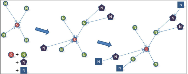
Figure 31: Installation Sequence
3.8Status Button Functionality
All GeoNet devices have red and green LED indicators to display their status. A reference key is printed on the side of each unit, below the LEDs. When pressed, the Status button triggers the appropriate LED indicators to briefly illuminate.
The table below shows the meaning of the various LED indications.
|
LEDs |
Gateway |
Loggers |
|
|
Green |
|
Time set, Loggers present |
GOOD: Radio signal > 30% |
|
Green |
Red |
Time set, no Loggers present |
MARGINAL: Radio signal < 30% |
|
|
Red |
Network time not set |
BAD: No radio signal |
table 7: LED Indicator Meaning
When the Status button is pressed on the gateway, the LEDs briefly display the network status. If the network is in Deployment mode when the button is pressed, the Deployment mode timer will reset. If the network is not in Deployment mode, it will enter Deployment mode on the following radio cycle. This could take up to six minutes, as changes to the radio settings can only occur when all the radios in the network are awake. In order to provide timely feedback to the user, the network parameters are set to a 10-second radio interval while the gateway is in Deployment mode.
When the Status button is pressed on a logger, the LEDs briefly display the radio signal status. The logger will indicate the status of the radio signal after each radio transmission for a period of 10 minutes. If a logger has not yet joined the network, it will change its radio interval to approximately one second and search for an available network.
|
Device |
Function |
Status Button Action |
|
Gateway or Logger |
Reset |
Press and hold until both LEDs illuminate (~10 seconds) |
|
Gateway |
Put the network into Deployment mode/extend Deployment mode. Display the current status. |
Press and release |
|
Gateway |
Take a reading and send existing data immediately |
Press and release |
|
Logger |
Display the current status, then indicate signal strength every radio cycle for 10 minutes |
Press and release |
table 8: Status Button Functions