5.Configuring Project Explorer Elements
Each project explorer element configurable settings. For some, like Workspace, Probe Library, and Project, the settings consist only of a name and description. Elements such as Holes and Probes require more configuration parameters such as English/metric units, initial level, and gauge factors. These settings can be adjusted to meet the user’s needs and the specifications of the probe. The software currently supports three different probe types and as many probe and hole configurations as the Field PC can store in memory. All these can be adjusted using the Edit Settings option from the Context or Application Menu.
Figure 108 depicts the Hole General Settings, the first screen of the Edit Hole Settings dialog. When done editing, the settings can be saved via the Menu->Save Settings option.
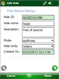
Figure 108: Hole General Settings
Hole ID:
Read-only value, generated when the hole was created. Used internally by the GK-604D IRA.
Hole name:
Tap the keyboard icon (bottom of the screen) to bring up the on-screen keyboard. Use it to enter a unique and descriptive hole name.
Description:
Optional parameter. Using the on-screen keyboard; enter a brief description pertaining to the hole’s location and purpose.
Probe Name:
Select the Probe Name from the drop-down list. This associates a hole with a particular probe. Enter "UNKNOWN" if the probe has not yet been "found".
Hole Units:
The units for the hole level and interval. Select either meters or feet from the dropdown list.
Created On:
Read-only date and time value, generated when the hole was created.
Starting Level:
Using the on-screen keyboard; enter a value for the initial level of the survey for this hole (see Figure 109).
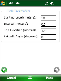
Figure 109: Hole Parameters
Interval:
Enter an interval to be used for the survey. This value is dependent on Hole Units and is typically a half-meter or two feet.
Top Elevation:
This optional parameter corresponds to the elevation at the top of the hole.
Azimuth Angle:
This optional parameter allows correction of any casing deviation from the appropriate A+ direction.
Figure 110 depicts the General Probe Settings, the first screen of the Edit Probe Settings dialog. When done editing, project settings are saved via "Menu->Save Settings" options.
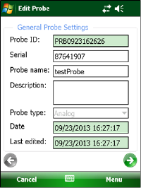
Figure 110: Probe General Settings
Probe ID:
Read-only value, generated when the probe was created. Used internally by the GK-604D IRA.
Serial number:
Read-only parameter. The read/write parameter is for obsolete analog systems.
Probe name:
Use the on-screen keyboard to enter a user friendly name for the probe.
Description:
Optional parameter. Enter a brief description pertaining to the probe.
Probe type:
Select a probe type from dropdown list. Choices are: Analog, Digital, Compass, and Tiltmeter.
Note: Analog mode is used only for obsolete analog GK-604 systems. Compass mode selects the geokon 6005-3 Spiral Indicator Probe, which is also an obsolete model, and requires the GK-604-3 Analog Reel System or the GK-604-4 Interface Module. In this mode, the GK-604D IRA will rescale the output to properly display 0-360 degrees on the Live Readings screen. In both Compass and Tiltmeter modes, only one channel (A) is read and displayed on the Live Readings screen, and only the A readings are stored in the data file. )
Date:
Read-only date and time value, generated when the probe was created.
Last edited:
Read-only data and time value, updated whenever the probe settings are modified.
Figure 111 depicts the Probe Coefficients Settings, the second screen of the Edit Probe Settings dialog. When done editing, project settings are saved via "Menu->Save Settings" options.
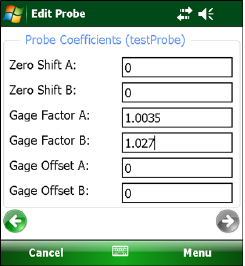
Figure 111: Probe Coefficients
A and B Channel Zero Shift:
To compensate for any offset at zero, enter appropriate values for the Zero Shift values. See the Inclinometer Probe manual and Calibration sheet for more information. Digital probes may have these values programmed at the factory. With the probe type set to Compass, the Zero Shift A value should be set to 200.
A and B Channel Gauge Factors:
Using the on-screen keyboard, enter appropriate numbers for the two gauge factors (see the Inclinometer Probe manual and Calibration sheet for more information). Digital probes may have these values programmed at the factory. With the probe type set to Compass, set the Gauge Factor A value to 0.1.
A and B Channel Gauge Offsets:
These values are typically "0" and are occasionally needed to remove an offset from a Compass probe. Offsets are entered in engineering units using the on-screen keyboard. For a Compass probe there will be no "B" channel and the B Channel value should be left at "0". Digital probes may have these values programmed at the factory.
When the probe type is set to Compass, the offset can be determined by taking readings (using the Live Readings screen) and determining if the compass value is ever greater than 360. If so, the Gauge Offset A value should be set to 360 – (current reading > 360). For example, if the current compass probe reading is 365 then the Gauge Offset A value = (360 – 365) = -5.
If the probe "Type" is set to Tiltmeter, the "B Channel" parameters are not used and can be left at 0. When done editing, the settings can be saved via the "Menu->Save Settings" option.
If connected to a digital Remote Module and digital probe, Zero Shift, Gauge Factor and Gauge Offset changes can be uploaded to the probe via the "Menu->Save and Upload Settings" option.
After tapping "Save and Upload Settings", the reminder window shown in Figure 112 will be displayed to ensure that the Remote Module is ready to connect.
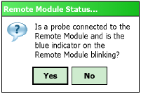
Figure 112: Ready for Connection?
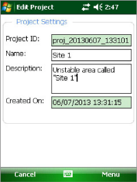
Figure 113: Project Settings
Project ID:
Read-only value, generated upon project creation. Used internally by the GK-604D IRA.
Project Name:
Use the on-screen keyboard to enter a unique and descriptive project name.
Description:
Optional. Use the on-screen keyboard to enter a brief description pertaining to the project.
Created On:
Read-only date and time value, generated when the project was created.