The basic units utilized by geokon for measurement and reduction of data from the vibrating wire deformation transducers used in the Model A-9 are "digits". The units displayed by the GK-404 and GK-405 in position "B" are digits. Calculation of digits is based on the following equation:
equation 1: Digits Calculation
To convert digits to deformation the following equation applies:
D = (R1 – R0) × G × F
equation 2: Deformation Calculation
Where;
D is the calculated deformation.
R1 is the current reading.
R0 is the initial reading usually obtained at installation (see Section 2.4).
G is the calibration factor, usually in terms of millimeters or inches per digit taken from the calibration report, an example of which is shown in Figure 6.
F is an optional engineering units conversion factor, see the table below
|
From To |
Inches |
Feet |
Millimeters |
Centimeters |
Meters |
|
Inches |
1 |
12 |
0.03937 |
0.3937 |
39.37 |
|
Feet |
0.0833 |
1 |
0.003281 |
0.03281 |
3.281 |
|
Millimeters |
25.4 |
304.8 |
1 |
10 |
1000 |
|
Centimeters |
2.54 |
30.48 |
0.10 |
1 |
100 |
|
Meters |
0.0254 |
0.3048 |
0.001 |
0.01 |
1 |
table 1: Engineering Units Conversion Multipliers
Example: The initial reading (R0) with no load on the pile of a Model 1300 (A-9) transducer is 5102 digits. The reading with a 100-ton load on the pile, the current reading (R1), is 4523. The calibration factor, G, is 0.0001755 inches/digit. The deformation change is:
D = (4523 – 5102) × 0.0001755 = -0.1016 inches
Note that decreasing readings (digits) indicate compression.
To calculate strain, divide the deformation by the distance between the anchors. For example, if the deformation change between two anchors spaced 12 feet apart was -0.1016 inches. The strain change for that segment of the pile, uncorrected for temperature, would be -0.1016/144 x 10^6 = -706 μstrain (compression).
6:
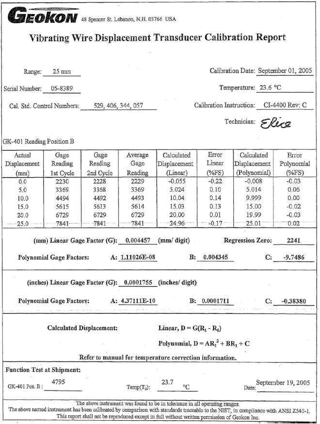
Figure 6: Typical Calibration Report
The Model 4430 Deformation Meter used in the Model 1300 (A-9) Extensometer has a vibrating wire transducer with a small coefficient of thermal expansion and the body of the transducer contracts and expands slightly with changes in temperature. The interconnecting rods also expand and contract; therefore, in most cases a correction is advisable. Note also that in situations where temperature changes are large (more than 10 degrees °C) it may be prudent to use carbon graphite rods that have very low coefficients of expansion. The following equation applies:
Dcorrected = (R1 – R0) × G + (T1 – T0) × K + LC + LR)
equation 3: Thermally Corrected Deformation Calculation
Where:
R1 is the Current Reading
R0 is the Initial Reading
G is the Calibration Factor
T1 is the Current Temperature
T0 is the Initial Temperature
K is the calculated Thermal Coefficient
LC is the correction for the change in gauge length
LR is the correction for the change in rod length
Tests have determined that the Thermal Coefficient (K) of the transducer changes with the position of the transducer shaft. The first step in the temperature correction process is determination of the proper Thermal Coefficient based on the following equation:
Thermal Coefficient = ((Reading in Digits Multiplier) Constant) Calibration Factor
Or
K = ((R1 × M) + B) × G
equation 4: Thermal Coefficient Calculation
See the table below for the multiplier and constant values used in the previous equation. The Multiplier (M) and Constant (B) values vary for the stroke of the transducer used in the Deformation Meter.
|
4450‑3 mm 4450‑0.125" |
4450‑12 mm 4450‑0.5" |
4450‑25 mm 4450‑1" |
4450‑50 mm 4450‑2" |
4450‑100 mm 4450‑4" |
4450‑150 mm 4450‑6" |
4450‑300 mm 4450‑12" |
|
|
Multiplier (M): |
0.000520 |
0.000375 |
0.000369 |
0.000376 |
0.000398 |
0.000384 |
0.000424 |
|
Constant (B): |
3.567 |
1.08 |
0.572 |
0.328 |
0.0864 |
-0.3482 |
-0.6778 |
|
Def Meter Length (L): |
267 mm 10.5" |
267 mm 10.5" |
267 mm 10.5" |
292 mm 11.5" |
393 mm 15.49" |
510.5 mm 20.1" |
715.2 mm 28.2" |
table 2: Thermal Coefficient Calculation Constants
The Model 4430 deformation meter length temperature correction (LC) is calculated using Equation 5.
LC = 17.3 × 10⁻⁶ × L × (T1 – T0)
equation 5: Deformation Meter Length Correction
Where L is the length of deformation meter in millimeters or inches, (see Table 2).
The rod length correction (LR) is calculated from the Equation 6:
LR= KR × S × (T1 – T0)
equation 6: Rod Length Temperature Correction
Where:
S is the distance between anchor points minus the length of the transducer in mm or inches.
KR is the coefficient of expansion of the rod material from the table below.
|
Rod Material |
KR Thermal Coefficient Per ºC |
|
Stainless Steel |
17.3 x 10⁻⁶ |
|
Graphite |
0.2 x 10⁻⁶ |
|
Fiberglass |
6.0 x 10⁻⁶ |
table 3: Thermal Coefficients of Expansion for Rod Materials
Example:
For the same 25 mm range transducer as before where the anchor spacing is 144 inches and the rods are fiberglass:
R1 = 4523
To= 15 degrees ºC
T1 = 30 degrees ºC
S= 144–10.5 = 133.5 inches
Then K = [4523 x 0.000369 +0.572] x 0.0001755 = 0.00039
The total temperature correction is:
(T1 – T0) [K + LC + LR ] = (30 – 15) x [0.00039 + 10.5 x 17.3 x 10-6 + 133.5 x 6.0 x 10-6] = +0.0206 inches
The total deformation, temperature corrected, is -0.1016 + 0.0206 = -0.081 inches, and the measured strain is -0.081/144 x 10^6 = -562 microstrain in compression.