Before assembly and installation of the extensometer, check the transducers for proper operation. See Section 3 for readout instructions. The GK-404 and GK-405 readouts the gauge will read between 2000 and 2500 in position B. The transducer may need to be slightly extended to get a reading. Pull on the Swagelok affixed to the transducer shaft to do this (see Figure 1).
Checks of electrical continuity can also be made using an ohmmeter. Resistance between the gauge leads should be approximately 180Ω, ±10Ω. Remember to add the cable resistance, which is approximately 48.5Ω per km (14.7Ω per 1000') of 22 AWG stranded copper leads at 20 °C. Multiply this factor by two to account for both directions. Resistance between the green and white conductors will vary based on temperature; see Appendix B. Resistance between any conductor and the shield or the case of the sensor should exceed two megohms.
Checks on the actuation of the anchor pistons must be done with care. The anchor must first be positioned inside a piece of pipe or tubing with an inside diameter of approximately 50 mm (2"), before the pistons are actuated by pneumatic pressure. If the pneumatic pressure is applied to the pistons while the anchor is not inside a tube, the pistons will over-range and in the process the o-ring seals will be damaged, and the pistons will then be unable to hold pneumatic pressure without leaking
Should any of these preliminary tests fail, see Section 5 for troubleshooting.
An adequate area must be located for the assembly of the extensometer. Preferably it should be as long as the extensometer, clear of debris and obstructions. When assembling the extensometer in the field be especially careful to keep dirt out of the Swagelok fittings for the inflation lines.
2:
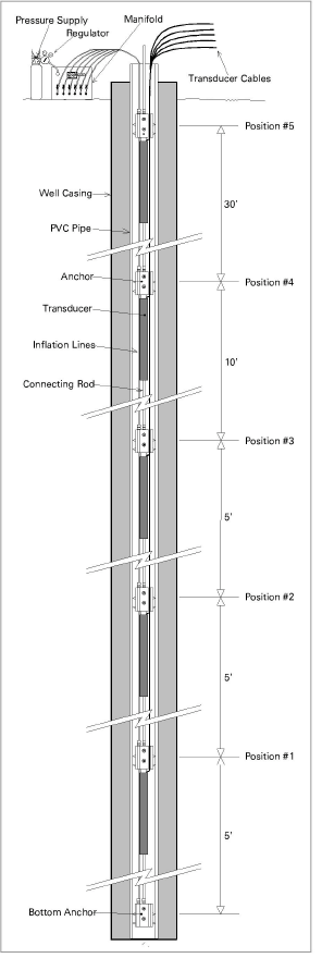
Figure 2: Model 1300 (A-9) Installation
1.Determine the anchor positions, i.e., the depth or position in the borehole for each anchor. Starting with the bottom (deepest) anchor, calculate the distance between it and the second anchor — this is the increment over which the measurement will be made.
2.The connecting rod must be cut to the proper length to make up this increment. For the standard 25 mm (1") transducer positioned at midrange, the length of the transducer assembly is 492 mm (19.375"). This length must be deducted from the increment length to make the correct rod length. For example, if the increment length is three meters, the rod length is 2.508 meters (3.0 - 0.492 = 2.508).
3.Calculate the rod lengths for all anchor positions and cut rods to length. Be careful when cutting the fiberglass rod that it does not splinter. Use a file to deburr the edges.
4.Connect the rod to the Swagelok fitting on the bottom anchor, pushing it in until it hits the shoulder. Tighten the Swagelok per instructions in Appendix D.
5.Connect the other end of the rod to the Swagelok fitting on the first transducer assembly. Repeat this for all the rods and sensors, leaving the instrument cables rolled up.
6.Attach an appropriate length of rod to the top anchor, this will allow for installation and removal of the system.
7.Cut nylon inflation tubing for each anchor position. Allow enough tubing to connect to the pressure manifold.
8.Attach to the Swagelok fitting for the inflation line and tighten per the instructions in Appendix D.
9.Lay out all the transducer cables and inflation lines next to the anchors and attached rods.
10. Position the lines and cables in the slots of the anchors and tape on either side of the anchors, i.e., tape above the anchor around the connecting rod and below the anchor around the transducer body. Continue this procedure at each anchor position from the deepest up to the top. Be sure the inflation lines and transducer cables are clearly labeled. Allow enough slack, at least the range of the instrument (25 mm / 1") between anchor positions for the movement of the anchors.
11.The assembly is now ready for installation in the borehole. Lower the assembly into the borehole with the bottom anchor first. Bend the connecting rod through a large arc, as needed to lower the extensometer. Be careful not to permanently bend the rods.
12.Once the assembly is installed, attach the inflation lines to the pressure manifold. Attach the transducer cables to the terminal box or multiplexer.
13.Make sure all the valves of the pressure manifold are in the off position.
14.Attach the air supply to the pressure manifold. Carbon dioxide, compressed air, or nitrogen may be used for the pressure supply. The recommended pressure for setting the extensometer is 300 psi (20 bar). Appendix C illustrates the relationship between applied pressure and pullout of the anchor. The maximum recommended applied pressure is 750 psi (50 bar).
15.Turn on the air for the deepest position of the extensometer.
16. Attach the readout to the instrument cable from the first transducer position.
17.To set the transducer anchor pull on the extension rod coming out of the borehole until the desired reading is obtained and then turn on the valve for that position. To set the instrument at midrange the reading should be around 5000 digits. To measure mostly tensile strains the reading should be around 3000. To measure mostly compressive strains the reading should be around 7000. Repeat this procedure for each transducer position of the extensometer.
The installation is now complete.
2.3Cable Installation and Splicing
The cable should be routed to minimize the possibility of damage due to moving equipment, debris or other causes. The cable can be protected using flexible conduit, which can be supplied by geokon.
Terminal boxes with sealed cable entries are available from geokon for all types of applications. These allow many gauges to be terminated at one location with complete protection of the lead wires. The interior panel of the terminal box can have built-in jacks or a single connection with a rotary position selector switch. Contact geokon for specific application information.
Because the vibrating wire output signal is a frequency rather than a current or voltage, variations in cable resistance have little effect on gauge readings; therefore, splicing of cables has no ill effects, and in some cases may in fact be beneficial. The cable used for making splices should be a high-quality twisted pair type, with 100% shielding and an integral shield drain wire. When splicing, it is very important that the shield drain wires be spliced together. Always maintain polarity by connecting color to color.
Splice kits recommended by geokon incorporate casts, which are placed around the splice and are then filled with epoxy to waterproof the connections. When properly made, this type of splice is equal or superior to the cable in strength and electrical properties. Contact geokon for splicing materials and additional cable splicing instructions.
Cables may be terminated by stripping and tinning the individual conductors and then connecting them to the patch cord of a readout box. Alternatively, a connector may be used which will plug directly into the readout box or to a receptacle on a special patch cord.
All readings are referred to the initial reading; it is very important that this initial reading be carefully taken. Conditions should be noted at the time of all readings, especially during curing, e.g., temperature, time after placement, local conditions, etc.
Care should be exercised when installing instrument cables to keep them as far away as possible from sources of electrical interference such as power lines, generators, motors, transformers, arc welders, etc. Cables should never be buried or run with AC power lines! The instrument cables will pick up the 50 or 60 Hz (or other frequency) noise from the power cable and this will likely cause a problem obtaining a stable reading.
The Model 1300 (A-9) Retrievable Extensometer, unlike numerous other types of instrumentation available from geokon, does not have any integral lightning protection components, i.e., transzorbs or plasma surge arrestors. Usually this is not a problem however, if the instrument cable is exposed, it may be appropriate to install lightning protection components, as the transient could travel down the cable to the gauge and possibly destroy it.
Note:
nIf the gauge is connected to a terminal box or multiplexer components such as plasma surge arrestors (spark gaps) may be installed in the terminal box/multiplexer to provide a measure of transient protection. Terminal boxes and multiplexers available from geokon provide locations for installation of these components.
nLighting arrestor boards and enclosures are available from geokon that install near the instrument. The enclosure has a removable top, allowing access to the protection board. If the LAB-3 is damaged, the user may service the components or replace the board. A connection is made between this enclosure and earth ground to facilitate the passing of transients away from the gauge. Consult the factory for additional information on these or alternate lightning protection schemes.
nPlasma surge arrestors can be epoxy potted into the gauge cable close to the sensor. A ground strap would connect the surge arrestor to earth ground, either a grounding stake or other suitable earth ground.