3.1Connecting The Mounting Blocks
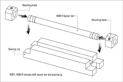
geokon vibrating wire strain gauges are held in place by two mounting blocks. geokon can provide mounting blocks, spacer bars, and spacing jigs for different gauge types and installations.
Assemble the mounting blocks onto the spacer bar as follows:
1.Fit the two mounting blocks over the ends of the spacer bar.
2.Position the mounting blocks and spacer bar onto the spacing jig.

3.Tighten the setscrews in the mounting blocks down onto the spacer bar so that it will not slide. Avoid tightening excessively, since this could damage the spacer bar.
4.Remove the completed mounting block and spacer bar assembly from the spacing jig.
3.2Installation on Steel Surfaces
Once the correct spacing of the mounting blocks has been set using the spacing jig, the mounting blocks may be welded to the steel surface as follows:
1.Clean the steel using a wire brush; remove all scale, rust, dirt, and oil.
2.Using the spacer bar as a handle, press the mounting blocks firmly against the steel surface.
3.Weld the edges of the mounting blocks in the order shown in the following figure.

Figure 3: Welding Sequence for the Mounting Blocks
Avoid excessive heat while welding. Do not weld the end surfaces of the mounting blocks; this would prevent removal of the spacer bar. Avoid welding splatter, which could stick to the spacer bar. When many gauges are being installed, it is advantageous to have more than one spacer bar available.
After welding, cool the mounting blocks with a water-soaked rag, then slacken the setscrews and slide out the spacer bar. Clean away all welding slag using a chipping hammer and wire brush.
Optional: Paint over the surface to provide some protection against corrosion.
Continue with the installation by proceeding to Section 3.5.
3.2.2Installation on Driven Steel Piles
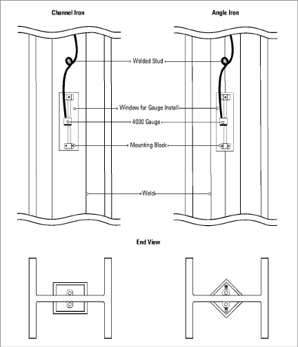
Strain gauges mounted on steel piles need to be protected from being scraped off as the pile is driven into the ground. This can be accomplished by welding 101 x 38 mm (4" x 1.5") channel iron or 64 mm (2.5") or larger angle iron over the top of the gauges and cables. For more, see Section 3.5.
To avoid burning the cables, the protection should be welded on before the gauges and cables are installed. To accomplish this, leave windows in the steel over the gauge locations. It is not necessary to use continuous welds; tack welding is sufficient so long as it holds the angles or channels firmly in place. Cables must be restrained by welding studs at three-meter intervals, to which the cables can then be tied.

Figure 4: Protection on Driven Piles
To prevent shock damage during driving, please observe these additional precautions:
□Install the mounting block that possesses the single setscrew in the upper position.
□Tighten hard the setscrews that hold the gauge in the mounting blocks. Use Loctite on the threads.
□Glue the coil onto the flat area of the gauge tube. (Use any cyanoacrylate product such as Eastman 910 or Crazy Glue.) Make sure that the cable side of the coil points towards the top of the pile, i.e., towards the end of the gauge with the V-groove.
□As an added precaution, tighten hard when installing the hose clamp that holds the coil on the gauge, and tighten using a nut driver.
□When setting the gauges make sure they are reading around 3500 on position C. This is very important.
Continue with the installation by proceeding to Section 3.5. After the gauges are installed, seal the windows by welding a section of the appropriate material over the window.
3.3Installation Using Epoxy Cements
geokon strain gauges can be epoxied to steel or concrete surfaces provided these two factors are strictly observed:
1.Proper care must be taken to clean the surfaces to be bonded.
2.Sufficient time must be allowed for the epoxy to cure before the gauges are attached to the mounting blocks.
Note: Due to the large number of variables associated with adhesive use (thermal cycles, UV exposure, vibration, impact, moisture, corrosion of base steel, etc.,) epoxy cement is recommended for short term monitoring only.
Materials needed:
■Devcon Underwater Putty, Mfg. Part# 11800 — geokon Part# 6201-2
■Loctite 410 Instant Adhesive, Mfg. Part# 41045 — geokon Part# 4000-15
1.Mix a quantity of the two-part underwater putty. The mix ratio is 1/1.
2.Grind and/or sand the surfaces to be bonded. (This includes both the concrete and the end block surfaces.)
3.Clean surfaces with compressed air or aerosol cleaner.
4.Attach the mounting blocks to the spacer bar, per the instructions in Section 3.1.
5.Apply a thin layer of mixed underwater putty to the center two-thirds of the mounting block, and a thin layer of 410 instant adhesive to the outside edges of the mounting blocks (see the figure below).

Figure 5: Installation Using Epoxy
6.Press the assembly firmly against the surface and hold in place for two minutes.
7.Carefully remove the spacing bar from the mounting blocks.
8.Allow 24 hours curing time before the gauges are installed.
9.Continue with the installation by proceeding to Section 3.5.
Use Loctite Speedbonder H4500. This can be purchased in a cartridge which automatically dispenses the two-part adhesive in its correct 10/1 mixture. (Adhesive, dispenser, and nozzles are available from geokon.)
Follow the instructions provided and then continue with the installation by proceeding to Section 3.5.
3.4Installing on Concrete Surfaces Using Anchor Studs
Strains in the surface of concrete can be measured by utilizing special mounting blocks that have reinforcing bar welded to them (geokon model 4000-5). Attach the strain gauge to the concrete surface as follows:
1.Drill two 64 mm (2.5") deep holes in the concrete at the proper spacing, using a minimum 13 mm (1/2”) drill bit. (A template is available, geokon model 4000-11.)
2.Connect the mounting blocks to the spacer bar using the spacer block (see Section 3.1).
3.Grout the rebar studs into the holes using fast-setting hydraulic cement or a high strength epoxy. Redhead epoxy, type Epcon Ceramic 6 works well.
4.Once the grout has cured, continue with the installation by proceeding to Section 3.5.

Figure 6: Installation on Concrete Using Groutable Anchors
Mount the strain gauge as follows:
1.Slide the strain gauge through the mounting blocks. The end of the gauge that has the V-groove goes inside the mounting block that has only one setscrew; the smooth end goes inside the mounting block with two setscrews.
2.Tighten hard the setscrew in the mounting block with only one screw.
3.Slide the slot in the coil assembly (located at the end of the instrument cable) over the narrow center of the gauge.
4.Connect the gauge to the readout box using the instructions in Section 6.2
5.Adjust the reading by pulling or pushing on the free end of the strain gauge.
6.Set the initial reading on the gauge to the correct level depending on whether compressive or tensile strains are anticipated. Strain gauges are shipped with a reading of approximately 3000 to 3500 microstrain. This level is okay for compressive strains. If tensile strains are to be measured, set the initial reading to around 1500 microstrain. The usable range of the strain gauge runs from around 1000 to 4000 microstrain. The midrange reading is 2500 microstrain.
7.When the desired reading has been achieved, tighten hard the setscrews in the mounting block with two setscrews.
8.Install the hose clamp over the assembly and tighten using a nut driver.
9.In order to remove any installation strains and stabilize the initial reading, tap on the mounting blocks with a hard plastic tool, e.g., the handle of a screwdriver. Continue tapping until the reading remains stable.
It is imperative that an accurate initial zero reading be obtained for each strain gauge, as this reading will be used for all subsequent data reduction.
It is preferable to install gauges on steel members while they are still in an unloaded condition, i.e., prior to their assembly into the structure. When the initial zero is established in this manner, the initial readings correspond to zero load, otherwise, if the member is under load the initial readings will correspond to some unknown load level.
Avoid excessive handling of the gauge prior to taking zero readings. Always allow sufficient time for the gauge temperature to stabilize before taking a reading. Be sure to record the temperature every time a reading is taken, along with notes concerning the construction activity that is taking place. This data might supply logical reasons for observed changes in the readings. (See also Appendix E and F.)
Each strain gauge has a thermistor encapsulated along with the plucking coil. geokon readout boxes display the temperature directly in degrees Celsius. An ohmmeter can also be used. (The relationship between resistance and temperature is shown in Appendix C.)