4.1Installation in Standpipes or Wells
1.Saturate the filter stone and establish an initial zero reading by following the steps outlined in Section 3.1 and Section 3.2.
Warning! Do not allow the piezometer to freeze once the filter stone has been saturated!
2.Mark the cable where the top of the well or standpipe will reside once the piezometer has reached the desired depth. (The piezometer diaphragm is located ¾ of an inch above the tip of the piezometer.)
3.Lower the piezometer into the standpipe/well.
4.Be sure the cable is securely fastened to prevent the piezometer from sliding further into the well and causing an error in the readings.
3:

Figure 3: Typical Level Monitoring Installation
It is not recommended that piezometers be installed in wells or standpipes where an electrical pump or cable is nearby. Electrical interference from these sources can cause unstable readings. If unavoidable, it is recommended that the piezometer be placed inside a piece of steel pipe. In situations where packers are used in standpipes, special care should be taken to avoid cutting the cable jacket with the packer, as this could introduce a possible pressure leak in the cable.
geokon piezometers can be installed in cased or uncased boreholes, in either single or multiple piezometer configurations. If pore pressures in a particular zone are to be monitored, careful attention must be paid to the borehole sealing technique.
The borehole should extend six to 12 inches below the proposed piezometer location. For installation methods A and B (below), if boreholes are drilled without using drilling fluid (mud), this drilling fluid should be of a type that degrades rapidly with time. Wash the borehole clean of drill cuttings.
Three methods of isolating the zone to be monitored are detailed below.
Installation A
Backfill the borehole with clean fine sand to a point at least six inches below the desired piezometer tip location. The piezometer can then be lowered into position. While holding the instrument in position, (a mark on the cable is helpful), fill the borehole with clean fine sand to a point at least six inches above the piezometer.
Immediately above the area filled with clean fine sand, known as the "collection zone", the borehole should be sealed by an impermeable bentonite cement grout mix, or with alternating layers of bentonite and sand backfill, tamped in place for approximately one foot, followed by cement-bentonite grout (see Figure 4).
If multiple piezometers are to be used in a single hole, the bentonite and sand should be tamped in place below and above the upper piezometers, as well as at interval between the collection zones. When using tamping tools special care should be taken to ensure that the piezometer cable jackets are not cut during installation, as this could introduce a possible pressure leak in the cable. For some installations, it may be cost effective to use a cement-bentonite grout between the multiple collection zones. It is recommended to hydrate the bentonite seals above and below the collection zones before placement of the grout.
Installation B
The borehole is filled from the collection zone upwards with an impermeable cement-bentonite grout. To keep the granular filter zone intact, care should be taken with this method to ensure that the grout does not bleed into the collection zone.

Figure 4: Typical Borehole Installations
Installation C
Since the vibrating wire piezometer is essentially a no-flow instrument, collection zones of appreciable size are not required. The piezometer can be placed directly in contact with most materials, provided that the fines are not able to migrate through the filter. As such, it is not necessary to provide collection zones of sand, and that the piezometer can be grouted directly into the borehole using only cement-bentonite grout.
The general rule for installing piezometers in this way is to use a grout mix that is similar to the parameters of the surrounding soil. Throughout the depth of a borehole, the surrounding soil will typically not be all of the same strength and permeability. However, the use of several types of grout mixes within the same borehole may not be cost effective and practical. Unless it is necessary to do so, identify one type of grout mix that would be applicable to the entire length of the borehole.
The emphasis for mixing grout should be on controlling the water-to-cement ratio, because this determines the strength characteristics of the mix. Do this by mixing the cement with the water first. The most effective way of mixing the two substances is to use a drill rig pump to circulate the mix in a 50- to 200-gallon barrel or tub.
Make the cement-bentonite grout using any kind of bentonite powder combined with Type I or Type II Portland cement. The exact amount of bentonite needed will vary somewhat. Table 1 shows two possible mixes for strengths of 50 psi and 4 psi.
|
50 PSI Grout for Medium to Hard Soils |
4 PSI Grout for Soft Soils |
||||
|
|
Amount |
Ratio by Weight |
Amount |
Ratio by Weight |
|
|
Water |
30 gallons |
2.5 |
75 gallons |
6.6 |
|
|
Portland Cement |
94 lb. (one sack) |
1 |
94 lb. (one sack) |
1 |
|
|
Bentonite |
25 lb. (as required) |
0.3 |
39 lb. (as required) |
0.4 |
|
|
Note: |
The 28−day compressive strength of this mix is about 50 psi, similar to very stiff/hard clay. The modulus is about 10,000 psi. |
The 28−day strength of this mix is about 4 psi, similar to very soft clay. |
|||
table 1: Cement / Bentonite / Water Ratios
Add the measured amount of clean water to the barrel then gradually add the cement in the correct weight ratio. Mix the cement thoroughly into the water, and then slowly add the bentonite powder so that clumps do not form. Keep adding bentonite until the watery mix turns to an slimy consistency. Continue mixing for approximately five to 10 minutes to allow the grout to thicken. Add more bentonite as required until it is a smooth, thick cream, similar to pancake batter, which is as heavy as it is feasible to pump.
When pumping grout (unless the tremie pipe is to be left in place), withdraw the tremie pipe after each batch, by an amount corresponding to the grout level in the borehole.
CAUTION! If the grout is pumped into the hole, rather than tremie piped, there is a danger that the piezometer will be over-ranged and damaged. Grout can also be segretate if pumped into top of borehole, and may not fully backfill and encapsulate the piezometer. It is good practice to read the piezometer while pumping.
For more details on grouting, refer to "Piezometers in Fully Grouted Boreholes" by Mikkelson and Green, FMGM proceedings Oslo 2003. Copies are available from geokon.
4.3Installation in Fills and Embankments
geokon piezometers are normally supplied with direct burial cable suitable for placement in fills such as highway embankments and dams, both in the core and in the surrounding materials.
For installations in non-cohesive fill materials, the piezometer may be placed directly in the fill, or, if large aggregate sizes are present, in a saturated sand pocket in the fill. If installed in large aggregate, additional measures may be necessary to protect the cable from damage.
In fills such as impervious dam cores, where subatmospheric pore water pressure may need to be measured, (as opposed to the pore air pressure), a ceramic tip with a high air entry value is often used. This type of filter should be carefully placed in direct contact with the compacted fill material. (See Figure 5).
Cables are normally installed inside shallow trenches with the fill material consisting of smaller size aggregate. This fill is carefully hand compacted around the cable. Bentonite plugs are placed at regular intervals to prevent migration of water along the cable path. In high traffic areas and in materials that exhibit pronounced "weaving", heavy-duty armored cable should be used.
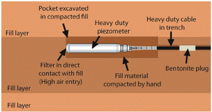
Figure 5: High Air Entry Filter
In partially saturated fills (if only the pore air pressure is to be measured), the standard tip is satisfactory. It should be noted that the standard coarse tip (low air entry) measures the air pressure when there is a difference between the pore air pressure and the pore water pressure. The difference between these two pressures is due to the capillary suction in the soil. The consensus is that the difference is normally of no consequence to embankment stability.
The coarse tip filter (low air entry) is suitable for most routine measurements. Both the installation shown in Figure 5 and the installation shown in Figure 6 may be used with the standard piezometer filter.
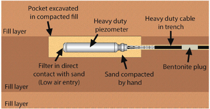
Figure 6: Low Air Entry Filters ONLY
4.4Installation by Pushing or Driving into Soft Soils
The Model 4500DP piezometer is designed to be pushed into soft soils. In soft soils, it can be difficult to keep a borehole open. The 4500DP may eliminate the need for a borehole altogether. The unit is connected directly to the drill rod (AW, EW, or other) and pressed into the ground, either by hand or by means of the hydraulics on the rig (see Figure 7). geokon suggests these units not be driven into the soil, since there is a possibility that the driving forces may shift the zero reading.
The ground conditions need to be relatively soft for the 4500DP to be effective. Soft soils (like clays or silts) with SPT blow counts under 10 are ideal. In stiffer soils, it is possible to drill a hole and then push the 4500DP only a few feet below the bottom of the hole. If the soil is too stiff, the sensor may overrange or break.
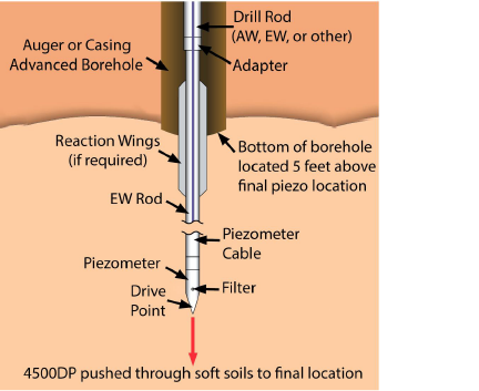
Figure 7: Typical Soft Soils Installation
The piezometer should be connected to a readout box and monitored during the installation process. If pressures reach or exceed the calibrated range, the installation should be stopped, and the pressure allowed to dissipate.
The drill rod can be left in place or it can be removed. If it is to be removed, a special five-foot section of EW (or AW) rod with reaction wings and a left-hand thread are attached directly to the piezometer tip. This section is detached from the rest of the drill string by rotating the string clockwise. The reaction wings prevent the EW rod from turning. A LH/RH adapter is available from geokon. This adapter is retrieved along with the drill string.
4.5Model 4500H and Model 4500HH Transducer
When connecting the Model 4500H transducer to external fittings, the fitting should be tightened into the 1/4-18 NPT female port by placing a wrench on the flats provided on the transducer housing. Avoid tightening onto a closed system; the process of tightening the fittings could overrange and permanently damage the transducer. If in doubt, attach the gauge leads to a readout box and take readings while tightening. For an easier and more positive connection to the transducer, PTFE (plumber’s) tape on the threads is recommended. The maximum pressure for the 4500H is 3 MPa.
The geokon Model 4500HH is designed for high-pressure environments. This model uses a 7/16-20, 60-degree, female, medium pressure fitting. The maximum pressure for the 4500HH is 75 MPa.
CAUTION! All high-pressure sensors are potentially dangerous. Care must be taken not to overrange them beyond their calibrated range. Sensors are tested to 150% of their range to provide a factor of safety.
4.6Splicing and Junction Boxes
Because the vibrating wire output signal is a frequency rather than a current or voltage, variations in cable resistance have little effect on gauge readings. Therefore, splicing of cables has no effect, and in some cases may in fact be beneficial. For example, if multiple piezometers are installed in a borehole, and the distance from the borehole to the terminal box or datalogger is great, a splice (or junction box) could be made to connect the individual cables to a single multi-conductor cable (see Figure 8). This multi-conductor cable would then be run to the readout station. For these types of installations, it is recommended that the piezometer be supplied with enough cable to reach the installation depth, plus extra cable to pass through drilling equipment (rods, casing, etc.).
Cable used for making splices should be a high-quality twisted pair type, with 100% shielding and an integral shield drain wire. When splicing, it is very important that the shield drain wires be spliced together. Splice kits recommended by geokon incorporate casts that are placed around the splice and then filled with epoxy to waterproof the connections. When properly made, this type of splice is equal or superior to the cable in strength and electrical properties. Contact geokon for splicing materials and additional cable splicing instructions.
Junction boxes and terminal boxes are available from geokon for all types of applications. In addition, portable readouts and dataloggers are also available. Contact geokon for specific application information.
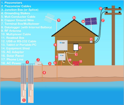
Figure 8: Typical Multi-Piezometer Installation
In exposed locations, it is vital that the piezometer be protected against lightning strikes. A tripolar plasma surge arrestor, which protects against voltage spikes across the input leads, is built into the body of the piezometer (see Figure 1).
Additional lightning protection measures available include:
■Placing a Lightning Arrestor Board (LAB-3), in line with the cable, as close as possible to the installed piezometer (see Figure 9). These units utilize surge arrestors and transzorbs to further protect the piezometer. This is the recommended method of lightning protection.
■Terminal boxes available from geokon can be ordered with lightning protection built in. The terminal board used to make the gauge connections has provision for the installation of plasma surge arrestors. Lightning Arrestor Boards (LAB-3) can also be incorporated into the terminal box. The terminal box must be connected to an earth ground for these levels of protection to be effective.
■If the instruments will be read manually with a portable readout (no terminal box), a simple way to help protect against lightning damage is to connect the cable leads to a good earth ground when not in use. This will help shunt transients induced in the cable to ground, away from the instrument.
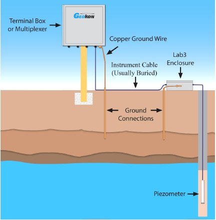
Figure 9: Recommended Lightning Protection Scheme
If the water around the piezometer freezes this could damage the piezometer diaphragm causing a large shift in the zero-pressure reading. If the piezometer is to be used in locations that are subject to freezing, geokon can provide a special modification that will protect the piezometer diaphragm.