Warning! Do not allow the piezometer to freeze once the filter stone has been saturated!
See Section 4.8 for information about protecting the piezometer from freezing.
Most filter tips can be removed for saturation and then reassembled. To maintain saturation, the unit should be kept underwater until installation. If the piezometer is used in a standpipe where it will be raised and lowered frequently, the filter housing may loosen over time, and a permanent filter assembly may be required. The removable filter may be fixed permanently by prick punching the piezometer tube approximately ⅟16" to ⅛" behind the filter assembly joint.
Salts in the water can be deposited into the filter stone causing it to become clogged if it is allowed to dry out completely. Filter stones may be replaced with screens for standpipe installations. Screens available from geokon are less likely than standard filters to collect salt and become clogged.
3.1.1Saturating Low Air Entry (Standard) Filters
For accurate results, total saturation of the filter is necessary. As the piezometer is lowered into the water, water is forced into the filter, compressing the air in the space between the filter stone and the pressure sensitive diaphragm. After a period, this air will dissolve into the water, filling the filter and the space above it entirely with water.
To speed up the saturation process, remove the filter from the piezometer by carefully twisting and pulling on the filter housing assembly (or unscrewing the point of the piezometer for model 4500DP). Hold the piezometer with the filter facing up and fill the space above the diaphragm with water. Slowly replace the filter housing, allowing the water to squeeze through the filter stone as it is installed. For piezometers with a range of less than 10 psi, take readings with a readout box while reinstalling the filter housing to ensure the piezometer is not over-ranged.
3.1.2Saturating High Air Entry Ceramic Filters
Because of the high air entry characteristics of the ceramic filter, de-airing is particularly important. Different air entry values require different saturation procedures.
One Bar Filters
1.Remove the filter from the piezometer by carefully twisting and pulling on the filter housing assembly.
2.Boil the filter assembly in de-aired water.
3.Reassemble the piezometer under the surface of a container of de-aired water. Use a readout box while slowly installing the filter to monitor the diaphragm pressure. If the piezometer begins to over-range, allow the pressure to dissipate before pushing further.
4.Be sure that no air is trapped in the transducer cavity.
Two Bar and Higher Filters
The proper procedure for de-airing and saturating these filters is somewhat complex; therefore, it is recommended that saturation be done at the factory by geokon. If saturation must be done in the field, carefully follow the instructions below:
1.Place the assembled piezometer, filter down, in a vacuum chamber that has an inlet port at the bottom for de-aired water.
2.Close off the water inlet and evacuate the chamber. The transducer should be monitored while the chamber is being evacuated.
3.When maximum vacuum has been achieved, allow de-aired water to enter the chamber until it reaches an elevation a few inches above the piezometer filter.
4.Close off the inlet port.
5.Release the vacuum.
6.Observe the transducer output. It may take up to 24 hours for the filter to completely saturate and the pressure to rise to zero.
7.After saturation, the transducer should be kept in a container of de-aired water until installation. If de-aired at the factory a special cap is applied to the piezometer to maintain saturation.
3.1.3Saturating Model 4500C Filter Tips
WARNING! The filter housing is not removable on the 4500C. Any attempt to remove the filter stone or the housing will destroy the transducer!
If the pressure to be measured is less than 5 psi the filter stone must be saturated. A hand operated vacuum pump and short length of half inch surgical tubing is required. Hand pumps and tubing are available from the factory. (A hand pump that has been used successfully is the MityvacII® by Lincoln Industries Corp. of St. Louis, MO.)
The saturation procedure is as follows:
1.Attach the tube to the transducer as shown in Figure 2.
2.Fill the tubing with approximately two inches (five centimeters) of water.
3.Attach the other end of the tube to the hand vacuum pump.
4.While holding the transducer so that the water rests on the filter, but does not enter the pump, squeeze the hand pump to initiate a vacuum inside the tubing. This will draw the air out of the filter and the area behind it, replacing it with water. A vacuum of 20 to 25" Hg. (50 to 65 cm Hg.) is enough for proper air evacuation.
2:
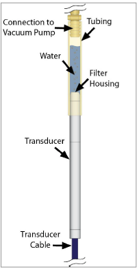
Figure 2: 4500C Saturation
3.2Establishing an Initial Zero Reading
Vibrating wire piezometers differ from other types of pressure sensors in that they indicate a reading when no pressure is exerted on the sensor.
Note: It is imperative that an accurate initial zero reading be obtained for each piezometer, as this reading will be used for all subsequent data reduction.
Generally, the initial zero reading is obtained by reading the instrument prior to installation. There are several different ways of taking an initial zero reading. The essential element in all methods is that the piezometer needs to thermally stabilize in a constant temperature environment while the pressure on the piezometer is barometric only. Because of the way the piezometer is constructed, it usually takes 15 to 20 minutes for the temperature of all the different elements to equalize.
A question may arise as to what to do with the filter stone while taking zero readings. It will not matter if the filter stone is saturated when using a standard stainless steel filter. However, if the piezometer is equipped with a ceramic high air entry filter stone, then it must be saturated while taking the zero readings.
It will be necessary to measure the barometric pressure only if the piezometer is unvented and it will be installed in a location that is subject to barometric pressure changes that would require correction, such as in an open well. In most instances, a piezometer sealed in place at depth will be affected by pressures in groundwater that is not hydraulically connected to the atmosphere, for which barometric pressure compensation would be inappropriate. See Section 6.3 for more information on Barometric corrections.
Calibration data is supplied with each gauge, a factory zero reading taken at a specific temperature and absolute barometric pressure is included. (See Appendix D for a sample calibration report.) Zero readings at the site should coincide with the factory readings within 50 digits, after barometric and temperature corrections are made. Barometric pressures change with elevation at a rate of approximately 3.45 kPa (½ psi) per 300 meters (1,000 ft). The factory elevation is +580 feet. All stated barometric readings represent absolute pressure uncorrected for height above sea level. A thermistor is included inside the body of the piezometer for the measurement of temperature.
NOTE REGARDING THE 4500C: The construction of this very slender vibrating wire transducer requires a miniaturization of the internal parts, which consequently are somewhat delicate. Handle the transducer with care during the installation procedure. Despite taking every precaution to ensure that the transducer arrives unharmed, it is possible for the zero to shift during shipment due to rough handling. However, tests have shown that though the zero may shift, the calibration factors do not change. Therefore, it is doubly important that an initial load zero reading be taken prior to installation.
3.2.1Recommended Method for Establishing an Initial Zero Reading
1.Saturate the filter stone per Section 3.1. Warning! Do not allow the piezometer to freeze once the filter stone has been saturated!
2.Replace the filter stone.
3.Hang the piezometer in the borehole at a point just above the water.
4.Wait until the piezometer reading has stopped changing.
5.Take the zero and temperature readings.
1.Place the piezometer under water in a bucket.
2.Allow 15 to 20 minutes for the temperature of the unit to stabilize.
3.Use the instrument cable to lift the piezometer out of the water. Do not handle the piezometer housing; body heat from the hands could cause temperature transients.
4.Immediately take a zero and temperature reading.
1.Allow 15 to 20 minutes for the temperature of the unit to stabilize.
2.Lift the piezometer by the cable only. Do not handle the piezometer housing; body heat from the hand could cause temperature transients.
3.Take a zero and temperature reading.
(If this method is chosen, be sure that the piezometer is protected from sunlight or sudden changes of temperature. Wrapping it in some insulating material is recommended.)
1.Lower the piezometer to a known depth marked on the piezometer cable. (The diaphragm inside the piezometer is located approximately 15 mm (¾") from the tip.)
2.Use a dip meter to accurately measure the depth to the water surface.
3.After temperature stabilization, read the piezometer pressure.
4.Using the factory calibration constants and a knowledge of the pressure of the water column above the piezometer (height times density), calculate the equivalent zero pressure reading if linear regression is used, or the factor C if the second order polynomial is used.
3.3Checking the Piezometer Performance
If a rough check of the piezometer performance is needed, the following procedure is recommended:
1.Lower the piezometer to a point near the bottom of a water-filled borehole, or below the surface of a body of water.
2.Allow 15 to 20 minutes for the piezometer to come to thermal equilibrium.
3.Using a readout box, record the reading at the current depth.
4.Raise the piezometer by a measured increment.
5.Record the reading on the readout box at the new depth.
6.Using the factory calibration factor, calculate the change in water depth.
7.Compare the calculated change in depth with the measured depth increment. The two values should be roughly the same.
Alternative method using a dip meter:
1.Lower the piezometer tip to a measured depth below the water surface.
2.Allow 15 to 20 minutes for the piezometer to come to thermal equilibrium.
3.Using a readout box, record the reading at that level.
4.Calculate the elevation of the water surface using the given calibration factor.
5.Compare the calculated elevation to the elevation measured using the dip meter.
things that can affect this checking procedure:
■If the density of the water is not one gram/cubic centimeter.
■If the water is saline or turbid.
■The water level inside the borehole may vary during the test. This is due to the displacement of water caused by the cable as it is raised and lowered in the borehole. The smaller the borehole is, the greater the displacement will be. For example, a Model 4500S-50KPA piezometer lowered 50 feet below the water column in a one-inch (0.875-inch ID) standpipe will displace the water level by more than four feet.
■Moisture on sidewalls of a casing can create friction that binds up the piezometer cable, such that it doesn’t move freely to the designated depth. Additional weight can be added to the piezometer if this bcomes an issue.