The digits displayed by the geokon Models GK-404, GK-405, and GK-406 readouts on channel B are based on the equation:

equation 2: Digits Calculation
Note that in the above equation, the period is in seconds; geokon readout boxes display microseconds. For example, a reading of 8000 digits corresponds to a period of 354 µs and a frequency of 2828 Hz.
Digits are directly proportional to the applied pressure, as can be seen by the following equation:
Pressure = (Current Reading – Initial Zero Reading) × Linear Calibration Factor
Or
P = (R1 – R0) × G
equation 3: Convert Digits to Pressure
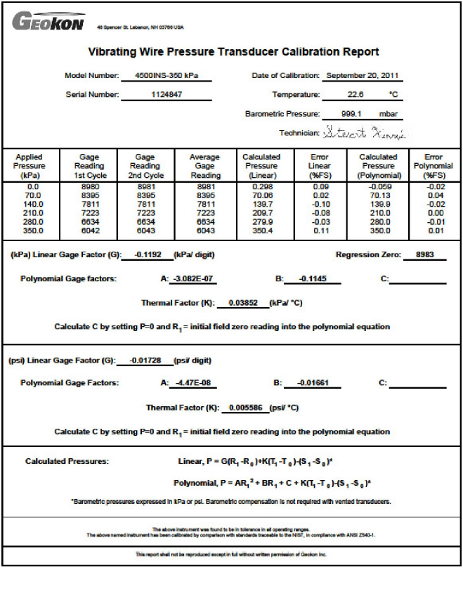
The Initial Reading (R0) is normally obtained during installation (usually the zero reading). The Calibration Factor (G, usually in terms of psi or kPa per digit) comes from the supplied Calibration Sheet (a typical calibration sheet is shown in Figure 18). To convert the output to other engineering units, multiply the Calibration Factor by the conversion multiplier listed in Table 3.
|
From To |
psi |
"H2O |
'H2O |
mm H20 |
m H20 |
"HG |
mm HG |
atm |
mbar |
bar |
kPa |
MPa |
|
psi |
1 |
.036127 |
.43275 |
.0014223 |
1.4223 |
.49116 |
.019337 |
14.696 |
.014503 |
14.5039 |
.14503 |
145.03 |
|
"H2O |
27.730 |
1 |
12 |
.039372 |
39.372 |
13.596 |
.53525 |
406.78 |
.40147 |
401.47 |
4.0147 |
4016.1 |
|
'H2O |
2.3108 |
.08333 |
1 |
.003281 |
3.281 |
1.133 |
.044604 |
33.8983 |
.033456 |
33.4558 |
.3346 |
334.6 |
|
mm H20 |
704.32 |
25.399 |
304.788 |
1 |
1000 |
345.32 |
13.595 |
10332 |
10.197 |
10197 |
101.97 |
101970 |
|
m H20 |
.70432 |
.025399 |
.304788 |
.001 |
1 |
.34532 |
.013595 |
10.332 |
.010197 |
10.197 |
.10197 |
101.97 |
|
"HG |
2.036 |
.073552 |
.882624 |
.0028959 |
2.8959 |
1 |
.03937 |
29.920 |
.029529 |
29.529 |
.2953 |
295.3 |
|
mm HG |
51.706 |
1.8683 |
22.4196 |
.073558 |
73.558 |
25.4 |
1 |
760 |
.75008 |
750.08 |
7.5008 |
7500.8 |
|
atm |
.06805 |
.002458 |
.029499 |
.0000968 |
.0968 |
.03342 |
.001315 |
1 |
.000986 |
.98692 |
.009869 |
9.869 |
|
mbar |
68.947 |
2.4908 |
29.8896 |
.098068 |
98.068 |
33.863 |
1.3332 |
1013.2 |
1 |
1000 |
10 |
10000 |
|
bar |
.068947 |
.002490 |
.029889 |
.0000981 |
.098068 |
.033863 |
.001333 |
1.0132 |
.001 |
1 |
.01 |
10 |
|
kPa |
6.8947 |
.24908 |
2.98896 |
.0098068 |
9.8068 |
3.3863 |
.13332 |
101.320 |
.1 |
100 |
1 |
1000 |
|
MPa |
.006895 |
.000249 |
.002988 |
.0000098 |
.009807 |
.003386 |
.000133 |
.101320 |
.0001 |
.1 |
.001 |
1 |
table 3: Engineering Units Multiplication Factors
For example, assume an initial reading of R0 = 9101, a present reading of, R1 = 7390 and a Calibration Factor of -0.1192 kPa/digit. The calculated pressure is:
204 kPa = (7390 -9101) × -0.1192
(Appendix D shows how a second order polynomial can be used to improve accuracy.)
Note: Due to changes in specific gravity with temperature, the factors for mercury and water in the above table are approximate.
The vibrating wire earth pressure cell is quite sensitive to temperature fluctuations but often temperature changes in the ground are minor and can be ignored. Corrections for temperature effects on the transducer alone can be made using the Thermal Factor (K) supplied on the calibration sheet (see Figure 18) along with an equation for its proper use. See Equation 4.
The temperature correction equation is as follows:
Temperature Correction = (Current Temperature – Initial Zero Temperature) × Thermal Factor
Or
Pcorrected = (R1 – R0) G + (T1 – T0) K
equation 4: Temperature Correction
The calculated correction would then be added to the pressure calculated using Equation 3. If the engineering units were converted, remember to apply the same conversion to the calculated temperature correction.
For example, assume an initial temperature of 25 °C, a temperature at the time of measurement of 12 °C and a Thermal Factor of +0.03852 kPa / °C. The thermally corrected pressure is:
203.5 kPa = 204 + (12 - 25) x 0.03852
Note that this correction for temperature applies only to the pressure transducer, not to the entire cell surrounded by soil or soil and concrete each with its own (different) temperature coefficient of expansion. Commercially it is not practical to measure this effect without incurring huge expenses. The effect is usually small at depths where the temperature is rather constant, but where temperatures do vary the effect can be quite large. For more information see Appendix D which gives a theoretical treatment.
In practice, the best way to compensate for temperatures is to derive a factor from simultaneous measurements of pressure and temperature at times when the temperature is changing and when it can be safely assumed that the applied load is not changing.
The pressure transducer used in geokon vibrating wire earth pressure cells is evacuated and hermetically sealed and will respond to barometric pressure fluctuation. If a correction for these fluctuations is required, then it is necessary to record the initial barometric pressure (S0) and the barometric pressure at the time of each reading (S1) and subtract the change (S1 - S0) from the calculated pressure reading.

Figure 19: Sample Model 4800 Calibration Sheet