geokon load cells are of an annular design primarily for use on tiebacks and rockbolts. They may also be used during pile load tests and for monitoring loads in cross-lot struts and tunnel supports, etc. In practically all cases, the load cells are used in conjunction with a hydraulic jack, which applies the load, and with bearing plates positioned on either side of the load cell.
geokon Model 4900 load cells are frequently used for the following:
■To provide a permanent means of monitoring the load throughout the life of the tieback, rockbolt, strut or support, etc.
■To provide an electronic output for automatic data gathering.
■As a check on the load as determined by the hydraulic pressure applied to the jack during proof testing on tiebacks, rockbolts, etc. For this purpose, the user should be aware that the agreement cannot be guaranteed better than ±20% because of the many variables.
Load cells are positioned so that the tensile load in the tieback or rockbolt produces a compressive load in the load cell. This is done by trapping the load cell between bearing plates positioned between the jack and the structure, either below the anchor plate for permanent installations or above the anchor plate for proof testing. Figure 1 and Figure 2 show the two different installations.

Figure 1: Load Cells on Tiebacks for the Permanent Monitoring of Loads
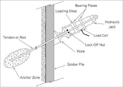
Figure 2: Load Cells on Tiebacks For Proof Testing Only
Figure 3 illustrates load cells being used for load monitoring during a pile load test.
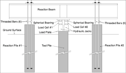
Figure 3: Load Cells for Load Monitoring During Pile Load Test
1.2Load Cell Design and Construction
The Model 4900 Load Cell body is constructed in the form of a high strength steel cylinder in which three to six vibrating wire strain gauges are embedded to measure the change of strain in the cylinder as it comes under load. Multiple gauges are needed to account for the effects of off-center or eccentric loading.
The cable is attached to the cell through a waterproof gland. A Kellem's grip strain relief prevents the cable from being pulled out of the cell. Cables have thick PVC jackets and can be terminated in a connector to mate with terminal boxes or readouts. See Appendix C for cable and connector diagrams. Figure 4 below shows a typical load cell.
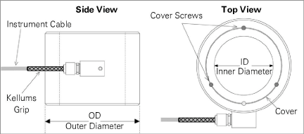
Figure 4: Model 4900 (Three Gauge) Load Cell
Additional cable protection can be obtained by either using armored cable or by placing the cable inside flex conduit. Figure 5 shows a typical load cell system.
.png)
Figure 5: Typical Load Cell System
Annular load cells, because of their design, are inherently susceptible to varying conditions of end loading, unlike solid load cells, which can be designed with button shaped ends so that the load always falls in a uniform, predictable fashion. Thus, the output and calibration of an annular load cell can be affected by the factors discussed in the subsections below. Note that all of these effects can be accumulative, and can cause the calibration to vary by as much as 20%, unless special precautions are taken.
1.2.1Friction Between the Bearing Plate and Load Cell
Friction between the bearing plate and the load cell can radically affect the performance of a load cell. Interposing deformable plates or lubricant between the bearing plates and the load cell in the field will cause the load cell to over-register, perhaps by as much as 10%. Again, for best results, it is important to calibrate the load cell in the laboratory under the same loading conditions as will be used in the field.
End effects of this nature can be reduced somewhat by using tall load cells. A rough rule of thumb for good load cell design calls for a load cell height at least four times the wall thickness of the loaded annulus. On some jobs where there are space restrictions calling for a pancake style load cell, friction between bearing plates and load cell can give rise to large hysteresis effects between loading and unloading cycles.
1.2.2Warping of the Bearing Plates and Bearing Plate Design
Warping of the bearing plates is caused primarily by a size mismatch between the hydraulic jack and the load cell. A jack larger than the load cell tends to wrap the intervening bearing plate around the load cell, causing the center of the load cell to "hourglass" or pinch inwards causing the load cell to under-register.
Conversely, a hydraulic jack smaller than the load cell will try to punch the intervening bearing plate through the center of the load cell, making the center of the load cell barrel outwards causing the load cell to over-register.
Both effects are exacerbated by bearing plates that are too thin. For further details on this topic, see Appendix D.
Note: To protect the lead wires routed in a groove in one face of the load cell geokon does not allow the use of a washer made from lead, copper, rubber or other soft material bearing against this surface. If a soft washer is used be sure it is used only on the other face, i.e., the one that does not have the annular epoxy-filled groove.
Minimum bearing plate thickness is 25 mm (1") where load cell size matches hydraulic jack size, i.e., the load bearing annulus of the load cell falls within the load bearing annulus of the hydraulic jack. For any other condition of size mismatch, the bearing plates should be at least two inches thick and even thicker where the size mismatch is extreme or the loads large.
Bearing plates should be flat and smooth. The normal rolled steel plate surface is adequate. It is not necessary to have machined or ground surfaces. Where plates are cut from larger plates, using cutting torches, the edges should be carefully cleaned to remove welding slag and solidified molten lumps.
Consideration should be given to calibrating the load cell using the same bearing plates as will be used in the field. In addition, it is possible to simulate the size of the hydraulic jack using a suitably sized metal donut between the upper platen of the testing machine and the upper bearing plate. Load cells calibrated in this way will be much more likely to agree with the hydraulic jack in the field.
Eccentric loading of load cells is the rule rather than the exception. Rarely is the axis of the tieback, rockbolt, or strut at right angles to the surface on which the anchor plate or strut rests. With tiebacks using multiple tendons, it is quite common for loads in individual tendons to vary markedly, despite best efforts to avoid this happening. In addition, struts are rarely at right angles to the soldier piles they may be supporting.
These factors combine to produce conditions in which the load cell experiences loads that are higher on one side than on the other. This effect is compensated for by the individual electrical resistance strain gauges, cemented to the cell, being connected together in a full Wheatstone Bridge circuit. Thus, the higher strains on one side are balanced by lower strains on the other and the average strain is not affected. Thus, even gross amounts of load eccentricity cause only slight (< 5%) variations in the load cell output and calibration.
Eccentric loading can be minimized by using spherical bearing plates, but this is expensive and is rarely done. Spherical seats may be of some value during pile load testing where uniformity of the load on the top of the pile is highly desirable.
It is important that a load cell behave elastically, i.e. that the no-load zero will not change with time. For this reason, use only the highest quality strain gauges and adhesives. geokon uses transducer-grade strain gauges, along with scrupulous observation of the best installation practices and adhesive post curing techniques.
geokon Model 4900 Load Cells are designed to keep the normal working stresses below 30% of the yield stress of the load cell material. Wherever possible load cells are cycled to 150% of the design load prior to calibration. As long as the load cell is never overloaded above this range, the no-load reading will not change. The normal over-range capacity of an aluminum load cell is 200% FSR and 300−400% FSR for a steel load cell before the load cell will begin to fail.
If a load cell is over-ranged and the no-load reading is shifted due to plastic yielding of the cell, then the cell should be returned to the factory for inspection and recalibration. Note, however, that while the no-load zero may shift, the calibration constant will probably not be affected.
Temperature compensation is achieved by using strain gauges whose thermal coefficient is the same as that of the load cell material. Normally, the temperature coefficient of the load cell is insignificant. In special cases, if required, the coefficient can be measured at the factory. Note that temperature changes on the loaded rockbolt, tieback, or strut can produce real changes of load and these will be recorded by the load cell. See Section 4.2 for more information on correcting for temperature.