It is important to have one set of grooves oriented down slope, in the direction of expected movement. If the direction cannot be determined, orient North/South. Alignment must be maintained throughout the installation, to avoid introducing torsion to the casing, thereby causing spiraling of the grooves. Never push the casing from the top or twist the casing during installation.
4:
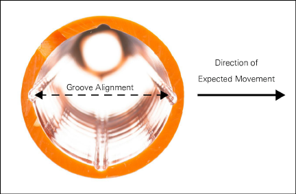
Figure 4: Groove Alignment
Insert the casing into the borehole one tube section at a time, using clamps to keep the sections positioned at the top of the borehole while you connect the sections. Use the provided Model 6600-2 Quick-Lock coupling wires to join the casing tube sections together. In dry boreholes, or in situations where down-hole problems seem likely, rig a safety line to provide extra security and a way to retrieve the casing if necessary.
1.Number each casing section to confirm correct depth placement and to assist with placement of any external instruments (such as vibrating wire piezometers).
2.There are two options for sealing the bottom of the casing:
nModel 6600-1B Bottom Cap or
nModel 6600-2A Casing Anchor Kit (sold separately)
If you plan on using the Model 6600-1B Bottom Cap, either:
nApply ABS cement to the inside of the cap and install it onto the tube, or
nUse self-tapping screws following the procedure outlined in Appendix B, steps 6 and 7.
Note: ABS cement must be supplied locally.
If you plan on using the Model 6600-2A Casing Anchor, refer to the instructions in Appendix B.
3.Attach a clamp to the tube near the coupling.
4.Lower the tube into the borehole, capped/anchored-end first, until the clamp rests on the borehole collar.
Caution: Casing alignment (end to end) is critical when joining casing sections together. If there is bending at the joints (especially critical during horizontal assembly), it is difficult to insert the Quick-Lock wire into the coupler hole and casing groove. In this case, move the casing sections back and forth at the joint until they align sufficiently to allow insertion of the Quick-Lock wire.
To maintain orientation of the casing sections, install the sections with one groove aligned toward anticipated direction of maximum movement (downslope or toward excavation).
1.Insert another casing tube section into the tube coupling.
5:
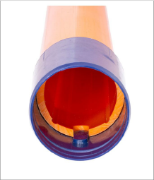
Figure 5: Coupling Tab
2.Rotate the tube inside the coupling while pushing downward. The notch at the end of the tube should slide onto the tab inside the coupling as shown:
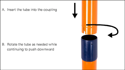
Figure 6: Connecting the Casing Sections
3.Insert a Quick-Lock coupling wire into the hole in the tube coupling. Keep threading the wire into the hole until you meet significant resistance.
Note: Keep the wire clean and wire hole free of debris to avoid clogging.
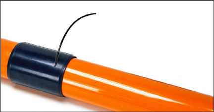
Figure 7: Secure with Model 6600-2 Quick-Lock coupling wire
Note: Model 6600-2 Quick-Lock coupling wire is sold in 406 mm (16") increments.
4.If desired, pull upward gently on the coupling to verify it is secure.
Note: For additional protection, wrap caulking tape around the the top of the coupler to seal the joint. Then wrap electrical tape around the caulking tape and then around the end of the wire to secure it to the coupler.
5.Attach another clamp to the tube near the free end, or as high as you can reach.
6.Remove the first clamp and lower the assembled section into the borehole, until the second clamp rests on the borehole collar.
7.If necessary, repeat steps 5-6 as needed until the free end of the tube is at an accessible height.
Repeat the steps in the Section 2.4 for the rest of the casing sections until you reach the desired depth.
If possible, verify the alignment of the grooves by running a dummy probe to the bottom of the hole. If the probe will not pass, jumps track, or returns in another set of grooves, pull the casing and check each tube section for proper alignment.
If the borehole is filled with water or drilling mud, filling the casing with clean water can neutralize the casing’s buoyancy, making it easier to submerge.
Additional weight may be necessary for boreholes with drilling mud, as the weight of the casing and the water may not be enough to overcome the buoyancy. Steel water pipe or clean chain can be carefully added into the casing (in such a way as to be retrievable) to provide additional down force.
Note: Be careful not to damage the bottom cap or sealed joint when lowering objects into the casing.
Caution: The differential pressure introduced by the head of water may cause the casing to fail if it exceeds the 15 bar (217 psi) burst capacity of the casing.
Buoyancy During Grouting
Casing also becomes buoyant during the process of grouting the borehole.
Use one of the following methods to prevent the casing from floating out of the borehole during grouting:
■Insert steel water pipe or clean chain inside the casing. Be careful not to damage the bottom cap or sealed joint when lowering solid objects down inside the casing.
■Grout the casing in stages:
nSecure the bottom of the casing with an initial batch of grout, letting it set up overnight.
nGrout the next section of casing, up to ground surface (if remainder of casing section can accommodate the pressure of the fluid grout).
■The Model 6600-2A Casing Anchor can resolve buoyancy issues, but it renders the installation permanent once deployed.
CAUTION: Applying a down force to the top of the casing will likely distort the casing profile. Never use the drill rig as a reaction force, or wedge into the collar of the borehole. Doing so can cause the casing to shift or "snake" within the borehole, which can affect the accuracy and precision of the inclinometer system.
Properly mixed grout must be thin enough to pump, but thick enough to set in a reasonable amount of time, and should be designed for the application. Very stiff grouts should not be used in a very soft soil formation, and similarly, a very soft grout mix should not be used for stiff soils or shoring wall systems.
Ensure that the grout is free of lumps. If the mixture is too watery, it will shrink excessively, leaving the upper portion of the borehole un-grouted. Avoid the use of grouts that cure at high temperature since these may damage the casing.
Use a tremie system to deliver the grout as directed by the engineer. Grouting, via a high shear filtered grouting machine is recommended to avoid problems with lumps obstructing the tremie tube.
The surface level of the water in the casing can indicate casing collapse or grout ingress. Grout ingress into the casing is likely to cause the water level to rise.
Note: Ensure that differential pressures are kept to a minimum, as the casing will collapse at 217 PSI differential.
Deeper boreholes will likely require a staged grouting procedure, with appropriate stages dependent on borehole water level, grout density, grout pump type, etc.
Note: Proper grouting of inclinometer casing is crucial to a successful inclinometer installation. The installer should have experience with grouting, and be able to work with the drill crew to determine the proper grout mixture. Grout consistency is very important to ensure proper curing, and to avoid separation of the solids and water. Grout with the proper viscosity is easier to pump.
Note: Site conditions can vary, making each inclinometer installation unique. Good judgment, by on-site personnel, and previous experience are the keys to success. geokon can provide suggestions on grout mixes based on the soil or rock type where the inclinometer application is to be installed.
2.8Installing the Model 6501-6-4 Protective Housing
The Model 6501-6-4 Protective Housing is grouted in place around the inclinometer casing where it protrudes from the ground. It consists of a 0.91m (3') × 100 mm (4") diameter galvanized steel pipe with lockable cap which threads onto the top of the steel pipe to protect the casing from vandalism.
8: .
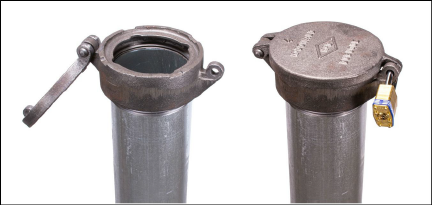
Figure 8: Model 6501-6-4 Protective Housing with Lockable Cap
When using the Model 6501-6-4 Protective Housing it will be necessary to extend the top of the casing above the top of the cap such that the pulley assembly can be attached.