Appendix B.Model 6600-2A Casing Anchor
geokon provides the following parts:
nCasing anchor
nO-ring
nFour self-tapping screws
nCaulking tape
9:
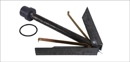
Figure 9: Anchor Kit Components
In addition, you will need the following parts:
nABS cement (locally-sourced)
nRelease cord of desired length, rated for 250 kg (500 lb).
Alternatively, geokon can provide part number 07-062G, galvanized aircraft cable 1.59 mm (1/16”) diameter for this purpose.
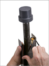
1.Use one hand to press the two anchor legs closed against the shaft of the anchor.
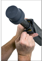
2.Slip the O-ring over the top of one leg. Be careful to avoid the sharp edge.
3.Stretch the O-ring around the pipe and loop it over the top of the other leg.
10:
|
|
|
Figure 10: Installing the O-Ring
11:
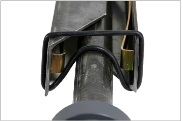
Figure 11: O-Ring Correctly Installed
12:
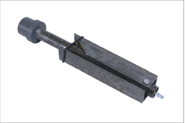
Figure 12: Anchor Ready for Mounting to Bottom Section of Casing
4.Apply ABS cement to the top of the anchor.
5.Insert the anchor into the open end of the tube.
13:
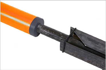
Figure 13: Installed Anchor
6.Use the self-tapping screws to secure the tube to the anchor.
14:
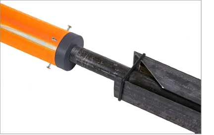
Figure 14: Install the Self-Tapping Screws
7.To prevent the entry of grout, use caulking tape and electrical tape to completely cover the screw heads and the seam where the bottom of the casing joins the top of the anchor.
15:
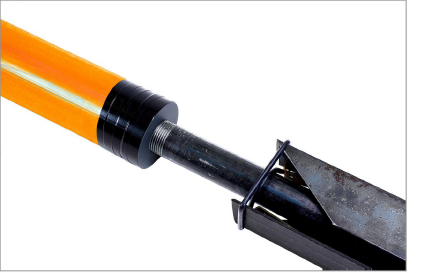
Figure 15: Installed Anchor with Tape for Grout Protection
8.Fasten the release cord onto O-ring, as indicated in the figure below.
16:
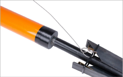
Figure 16: Release Cord, made using geokon part number 07-062G
9.Lower the casing into the borehole. Feed the release cord with the casing as you lower it.
For detailed instructions on installing the casing into the borehole, see Section 2.
Do the following when the casing reaches the desired depth:
1.Pull the release cord to dislodge the O-ring from the anchor legs, which then expand into the surrounding earth, holding the anchor in place.
2.Remove the entire length of release cord from the borehole.
3.Backfill the borehole with grout as necessary.
