2.Introduction
The GK-604D is made up of four components: An Inclinometer Probe, the Readout Unit, the Remote Module, and a Pulley Assembly.
The standard model is the 6100D digital probe (see Figure 5). In addition to standard inclinometer probes, the GK-604D IRA can be used with geokon Model 6101D Tiltmeter. (See Appendix G for more information on Model 6101D Tiltmeters.)
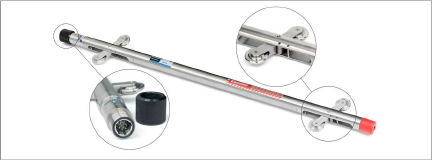
Figure 5: 6100D Digital Probe
■Features Include:
■Waterproof, stainless steel housing.
■Rubber cushion on base to reduce shock.
■Superior quality, hermetically sealed connector with gold plated pins.
■Protective cap for connector when not in use.
■Replaceable wheels.
■Model 6100D Digital Probes feature a built-in compass.
The Readout Unit consists of a handheld field PC (Model FPC-2), running the GK-604D Inclinometer Readout Application (see Figure 6).
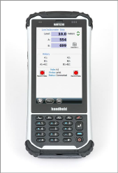
Figure 6: FPC-2 Running GK-604D IRA
Features Include:
■Rugged
■Reliable
■All the benefits of a Windows Mobile compatible device (Windows file system, RS-232, USB and Bluetooth connectivity)
■Long battery life
■Ease of use
2.2.1GK-604D Inclinometer Readout Application
The GK-604D Inclinometer Readout Application (GK-604D IRA) installs and runs on a rugged handheld PC, Model FPC-2, (see Figure 6) and is designed to communicate via Bluetooth with Remote Modules connected to digital MEMS probes.
Note: The GK-604D Inclinometer Readout Application will also operate on the Archer 2 and Archer Field PC from Juniper Systems, as well as the Nautiz X7 (geokon Model FPC-1).
The GK-604D Remote Module is housed in a weatherproof reel enclosure containing the cable (see Figure 7), which connects directly to the inclinometer probe (see Figure 5). The Readout Unit and Remote Module components communicate wirelessly using Bluetooth®, a reliable digital communications solution. This simplifies the handling of the system in the field as well as simplifying the transfer of data to your PC workstation for final analysis.
For digital probes, the Remote Module is fully contained within the reel as depicted below.
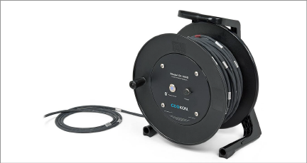
Figure 7: GK-604D Remote Module
Features Include:
■Lightweight
■Easy to use, one button operation.
■Rugged
■Lithium battery (Eight+ hours of continuous use)
■Automatic power down when the Bluetooth connection is dropped or after several minutes of inactivity.
■Reliable connection to standard inclinometer probes (shown in Figure 5) is accomplished via model 6001-2 control cable (see Figure 8), which features a lightweight, polyurethane jacket and is 8 mm in diameter. The control cable contains a central stainless steel aircraft wire and has breaking strength of 500 lb.
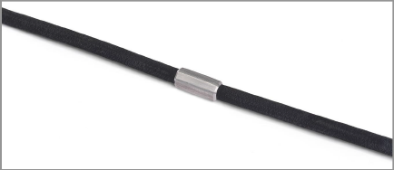
Figure 8: Model 6001-2 Control Cable
A pulley assembly (see Figure 9) is used to grip the control cable. The pulley places no stress on the cable markers and removes any tendency for markers to slip over the cable as when using cable holds.
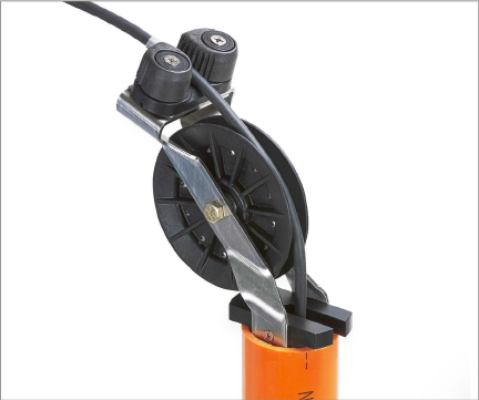
Figure 9: Pulley Style Cable Grip
The pulley assembly is designed to fit casing sold by geokon but will also fit most casings that have an internal diameter between 82 mm (3.25") and 59 mm (2.33"). When using casing that has an approximate I.D. of 76 mm (3"), the pulley assembly may be set directly into the top of the casing without adjustment. For all other casing sizes, complete the following:
Using the screwdriver provided, turn each of the three adjustment screws counter-clockwise, until they are recessed enough to allow the outer collar to be removed. Figure 10 and Figure 11 shows the collar removal sequence.

Figure 10: Turn Adjustment Screws

Figure 11: Remove Outer Collar
Next, turn the adjustment screws clockwise until they are set so that the cable hold will fit into the casing with as little movement as possible when it is seated. (All three screws should protrude approximately the same amount; this ensures that the pulley assembly is centered in the casing.) Figure 12 shows the adjustment screws at their full extension.

Figure 12: Adjustment Screws Extended