Appendix G.Dual Channel Digital Tiltmeter (Model 6101D)
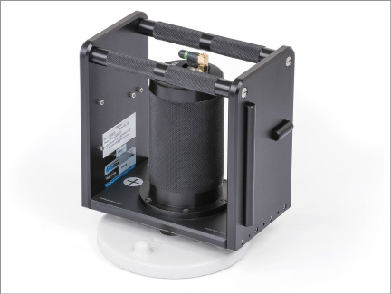
The Model 6101D Tiltmeter contains an integral battery and Bluetooth connectivity module, allowing the tiltmeter to be read directly with the FPC-2 running the GK-604D IRA. No external Interface Module is needed. The Model 6101D can also measure tilt in two axes: A and B.

Figure 119: Model 6101D Digital Tiltmeter
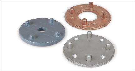
The Model 6101D Portable Tiltmeter is designed to be placed on an alignment plate/tiltplate (see Figure 120) that has been permanently attached to the structure being monitored. Measurements can be made on horizontal or vertical surfaces. The readings are taken in pairs, 180 degrees apart, to eliminate any instrument bias and thereby obtain true tilt.

Figure 120: Tiltplates: 6201-1C (Ceramic), 6201-1A (Copper Plated Aluminum), 6201-1S (Stainless)
It is assumed that a valid Bluetooth pairing exists between the 6101D and the FPC-2 (see Section 3.3 for more information about establishing Bluetooth pairings).
The recommended steps for connecting to and taking a reading with the Model 6101D Tiltmeter are as follows:
1.Create an initial "hole" configuration corresponding to the unique location where tilt is to be measured:
nHighlight the Project element and select the "Add Hole" menu item to create a new configuration (see Section 4.2.1, Context menu).
nSince the "hole" corresponds to a physical location, be sure to name it appropriately, such as, "Location1".
nAdditional information may be entered in the "Description" field.
nFor the first hole created, select "UNKNOWN" for "Probe name:".
nHole parameters "Starting Level", "Interval", "Top Elevation" and "Azimuth Angle" are not applicable for tiltmeter operation.
nTap "Save Settings" to save the new location (hole) configuration. See Section 5.1 for more information about hole configuration.
2.Make sure that the "hole" corresponding to the location to be measured is selected in the Project Explorer.
3.Press the ON/OFF button on the 6101D and ensure that the blue indicator light is blinking.
4.Tap the Live Readings menu item from the Application menu to start the reading process. If a valid Bluetooth connection can be established, a dual axis, tiltmeter specific, Live Readings screen will be displayed.

Figure 121: Live Readings (Tiltmeter)
Note: The dropdown control located to the right of the "A" value display allows the "A" and "B" values to be displayed in three different units, described below:
Digits:
Digit values are read directly from the 6101D Tiltmeter and are internally calculated as follows:
R1 = internal MEMS module voltage, (volts)
R0 = Zero Shift A [from internal probe configuration]
GF = Gauge Factor A [from internal probe configuration]
GO = Gauge Offset A [from internal probe configuration – usually zero]
DIGITS = (((2500 * R1) – R0) * GF) + GO
Volts:
PV = DIGITS / 2500 [for geokon tiltmeters: +4V ≈ +15 degrees]
Degrees:
DEGREES = arcsin(DIGITS / 38637.03305)
[multiply by 180/Pi if arcsin produces angles in radians]
5.Align the Tiltmeter on the tiltplate in the A+ orientation, then tap "Record Data" to take the A+ reading (see the 6101 User’s Manual). For the Model 6101D, the B+ reading is taken at the same time as A+.
6.Tap the Dataset icon and observe that the dataset number changes to 2.
7.Reverse the Tiltmeter orientation to A- and, again, tap "Record Data" to take the A- reading. For the Model 6101D, the B- reading is taken at the same time as A-. Tap "Menu-›Exit Live Readings" to display the window below:

Figure 122: Save Data Query
8.Tap the Yes button to start the data saving process. The Save File dialog (Figure 123) displays, allowing the user to name the data file to save.

Figure 123: Save File Dialog
9.After tapping "Save", the GK-604D IRA will determine if the file exists. If this is a new file, then the data will be written to it in a format similar to the standard Inclinometer format. If a file of the same name already exists, then the dialog shown below displays.

Figure 124: File Exists Dialog
10.Tapping "Yes" on the "File exists" dialog allows multiple reads for this location to be stored in a single data file. See Appendix G.1 for an example of Dual Axis Tiltmeter data format.
11.Tapping "No" at the "File exists" dialog will again call up the "Save File" dialog (see Figure 123) and another opportunity will be given to select a new file.
G.1Dual-Axis Tiltmeter Data Format
|
*** |
|
GK 604E(v1.3.0.0,02/15);2.0;FORMAT II |
|
PROJECT: Site 1 |
|
LOCATION: Loc1 |
|
DATE: 2/19/15 |
|
TIME: 14:54:17 |
|
PROBE NO.: tiltMeter |
|
UNITS: DIGITS |
|
FILE NAME: Loc1_Tiltmeter.gkn |
|
A+, A-, B+, B-, Date/Time |
|
-1358, 1587, 55, -58, 2/19/15 14:50:25 |
|
-1477, 1600, 55, -58, 2/21/15 14:45:07 |
|
-1458, 1557, 53, -56, 2/23/15 14:30:15 |
|
-1555, 1696, 57, -51, 2/25/15 14:37:33 |
table 17: Dual-Axis Tiltmeter Data Format