3.Installation And Operation
3.1Before Using the GK-604D Inclinometer Readout
The readout software runs as an application under Windows Mobile 6 operating system (OS) installed on a handheld PC (FPC-2).
Note: See Section 1 for inclinometer equipment setup, measurement procedures, and inclinometer theories. The user should familiarize themselves with the FPC-2 and the Windows Mobile OS.
■Use the Start button, File Explorer, and the Bluetooth Settings manager to launch applications.
■Tap the keyboard icon to use the on-screen keyboard to enter text and numbers.
■Review the Maintenance requirements in Section 7.
If all parts of the GK-604D system were purchased as a system from the factory, continue to Section 3.2.
If the handheld PC was purchased from geokon as a separate item (without cable and probe) refer to Section 3.5.
If using a handheld PC that was not purchased from geokon, skip follow the instructions in Section 3.3 and Section 3.4.
3.2Initial Quick Start Sequence
The steps described in this section are an attempt to guide the user through the process of launching the GK-604D IRA, connecting to the probe, and taking a survey.
The following steps are a guide to the typical operation of the GK-604D and, if followed, should result in a successful "hole" survey being taken.
Note: Always make sure that the inclinometer probe is attached to the reel before attempting the quick start sequence below.
1.Launch the GK-604D IRA by tapping on "Start" from the FPC-2 main window, tap "Programs", then tap the GK-604D IRA icon.
2.The Main Window shown in Figure 13 will be displayed. (If prompted to create a workspace name, refer to Section 3.5)
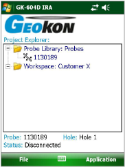
Figure 13: User Interface
3.Tap and hold on the workspace to bring up the context menu. Select "Add Project" to create a new project within the workspace.
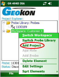
Figure 14: Add Project
4.The Projects Settings dialog will be displayed (see Figure 15).
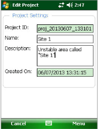
Figure 15: Project Settings
Project Settings are as follows:
Project ID: Read-only value, generated upon project creation. Used internally by the GK-604D IRA.
Project Name: Use the on-screen keyboard to enter a unique and descriptive project name.
Description: Use the on-screen keyboard to enter a brief description pertaining to the project.
Created On: Read-only date and time value, generated when the project was created.
5.When done editing the project settings, tap "Menu" then "Save Settings".
6.After creating a project, tap and hold on the project icon to bring up the context menu. Select "Add Hole" to create a new hole within the project.
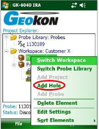
Figure 16: Add Hole
7.The Hole Settings dialog will be displayed.
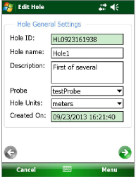
Figure 17: Hole General Settings
The Edit Hole Settings dialog contains the following:
■Hole ID: Read-only value, generated when the hole was created. Used internally by the GK-604D IRA.
■Hole name: Tap the keyboard icon (bottom of the screen) to bring up the on-screen keyboard. Use it to enter a unique and descriptive hole name.
■Description: Optional parameter. Using the on-screen keyboard; enter a brief description pertaining to the hole’s location and purpose.
■Probe Name: Select the Probe Name from the dropdown list. This associates a hole with a particular probe. Enter "UNKNOWN" if the probe has not yet been "found".
■Hole Units: The units for the hole level and interval. Select either meters or feet from the dropdown list.
■Created On: Read-only date and time value, generated when the hole was created.
To see the second screen of the edit hole settings, tap the green arrow ![]() . The second screen contains the following:
. The second screen contains the following:
■Starting Level: Using the on-screen keyboard; enter a value for the initial level of the survey for this hole.
■Interval: Enter an interval to be used for the survey. This value is dependent on Hole Units and is typically a half-meter or two feet.
■Top Elevation: This optional parameter corresponds to the elevation at the top of the hole.
■Azimuth Angle: This optional parameter allows correction of any casing deviation from the appropriate A+ direction.
8.When done editing the hole settings, tap "Menu" then "Save Settings".
9.Select the new hole by tapping on the icon.
10.Press the button labeled "POWER ON/OFF (BLUETOOTH)" on the Remote Module. A blue light should come on and start to blink, signifying that the Remote Module is waiting to connect to the FPC-2 unit.
11.To start the connection process, tap the Application Menu, then tap "Live Readings" (see Figure 18).
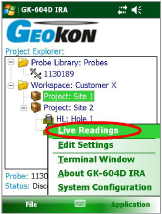
Figure 18: Application Menu
12.After few seconds, the blue light on the Remote Module should change to a steady state blue (lit but not flashing) and the Live Readings Window will be displayed (see Figure 19).
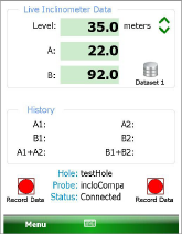
Figure 19: Live Readings Screen
13.Refer to Section 4.3.1 for more information about taking a survey using the Live Readings window. Also, refer Section 1.2 for information regarding the mechanical process of taking a survey.
14.After performing a survey, any saved data corresponding to a particular hole survey may be reviewed and/or reports generated by tapping the File menu then "View Data". See Section 4.4.3 for more information about the View Data option.
15.Raw data files may be exported to a file system folder of the user’s choosing by tapping on "File", then "Export", then "Data". See the Export Data Menu for more information regarding data export options.
16.To close the GK-604D IRA, tap "File" then "Exit".
3.3Establishing Contact With The Remote Module
geokon makes every effort to ensure that the system is completely set up and working before it leaves the factory. This includes the Bluetooth pairing between the Field PC and the Remote Module. When purchased as a system from the factory Section 3.3 through Section 3.5 may be skipped.
In general, this should only need to be done once and is typically done before it leaves the factory. Follow the steps below to ensure the ‘partnership’ with the remote is established before using the readout software:
Use the Bluetooth Settings Manager on the handheld PC to set up the link to the remote. Read about setting up a Bluetooth "partnership" in Chapter 9 of the Field PC’s Reference Guide. See the diagrams below for two examples of how to start Bluetooth Manager.
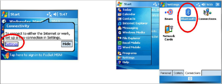
Figure 20: Starting Bluetooth Manager
Once in the Bluetooth Settings Manager, click on the "Mode" tab and then make sure that the box next to "Turn on Bluetooth" is checked (see Figure 21).
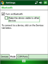
Figure 21: Turn on Bluetooth
Click on the "Devices" tab. If it shows a "geokon" device (name will start with "GK-604" and contain the remote’s serial number), go to step six. Otherwise turn on the remote module (should see a flashing blue indicator on the remote) and select "Add new device…".
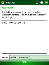
Figure 22: Add New Device
When a suitable remote is discovered, highlight the device and tap "Next" (see Figure 23).
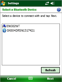
Figure 23: Select a Bluetooth Device
A prompt will be displayed for a password; tap "Next". If a partnership with the device is successfully established the screen will momentarily display the prompt shown at the bottom of Figure 24 and then return to the Bluetooth Devices screen. Click "Cancel" on the "Enter Passcode" screen then click "Done".
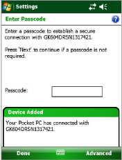
Figure 24: Enter Passcode
Click on the COM Ports tab. If the "geokon" device is already assigned to a COM Port, skip to step nine. If no COM port is assigned, select "New Outgoing Port". In the example shown in Figure 25, there is no COM Port assigned to a "GK604" device.
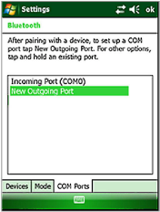
Figure 25: New Outgoing Port
Figure 26 shows the devices that a COM Port may be selected for. Select the appropriate "geokon" device from the list and tap "Next".
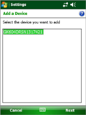
Figure 26: Add a Device
From the "Port:" dropdown list, select COM6, COM7, or COM8. (The other COM Ports are used by the system and are not available.) Be sure to remember the number of the COM port as you may have to select it later in the readout software (see Section 4.3.1 and Section 4.3.2, as well as Figure 48). Make sure to "uncheck" the "Secure Connection" check box (see Figure 27). Tap "Finish" when done to return to the Bluetooth Settings "COM Ports" screen.
Note: If using a Nautiz X7, COM5 may be available, depending on the model.
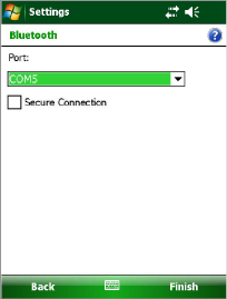
Figure 27: COM Port Selection
Lastly verify that the Bluetooth device is set for Serial Port operation. From the "Devices" tab of the Bluetooth Settings manager, tap the device to be used to communicate with the remote. Figure 28 will display. Ensure that the "Serial Port" checkbox is checked. Tap "Save" to complete the Bluetooth Settings.
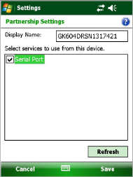
Figure 28: Serial Port Check Box
Note: After "Save" is selected, you will be brought back to the "Devices" window. There will be a Connect button available at the bottom of the screen. See Figure 29 below.
DO NOT USE THE "CONNECT" BUTTON TO TEST THE CONNECTION!
It will always fail after the pairing has been made successfully. Test the pairing by entering the GK-604D_IRA application.
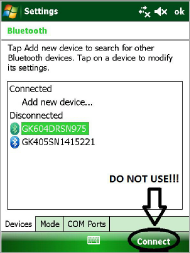
Figure 29: Connect Button
The installation of the GK-604D IRA requires a Handheld device (HHD) running Windows Mobile Classic 6.0 or higher, with at least 50 Mbytes of free memory. HHD must be Bluetooth enabled and be able to assign a Bluetooth connection to a COM port. Windows .NET 3.5 Compact Framework (CF) and .NET framework English-language Messages package installed on HHD. Both "CAB" file installers are included in the GK-604D IRA installer "Zip" file, available on geokon’s website (http://www.geokon.com/digital-inclinometer-system/).
Also required is Microsoft ActiveSync version 4.5.0 or higher running on the host PC (see Figure 30) or Windows Mobile Device Center if PC is running Windows 7 (see Figure 31) as well as the HHD. An active connection between the two must be established via either a physical link or Bluetooth.
Note: For customers using a PC running Window 10 operating system; Windows Mobile Device Center (WMDC) may no longer operate as it should because of an operating system update (released October of 2017) called "Fall Creator Update". If WMDC no longer launches when a mobile device is connected via USB cable or will not manually launch, the link below should help fix the issue. Please note that administrative privileges are needed to launch some of the files involved in the fix so your local IT person may need to be involved. The fix can be accessed via the following link:
https://www.handheldgroup.com/support-rugged-computers/knowledgebase-KB/22996/
Should the link above fail to fix the WMDC launch problem, the link below offers another possible solution:
http://www.junipersys.com/Juniper-Systems-Rugged-Handheld-Computers/support/Knowledge-Base/Support-Knowledge-Base-Topics/Desktop-Connection-ActiveSync-or-Windows-Mobile-Device-Center/WMDC-in-Windows-10
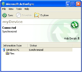
Figure 30: ActiveSync Window Showing Active Connection
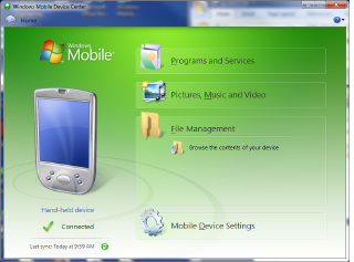
Figure 31: Windows Mobile Device Center
3.4.1Launching the GK-604D Installer
From the Windows Mobile Device Center window on a desktop PC (see Figure 31), click on the folder icon labeled "Browse the contents of your device" to call up an Explorer Window for the HHD (see Figure 32). The procedure for ActiveSync is very similar.
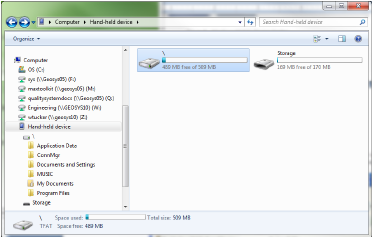
Figure 32: Windows Explorer Window Displaying HHD Root Folder
In the Explorer Window, double-click the icon labeled "\" to navigate to the handheld PC’s system root shown in Figure 33.
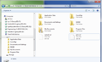
Figure 33: Handheld Device Root Folder Contents
Unzip the GK-604D Installer (downloaded from geokon’s website), open a Windows Explorer window, and then navigate to the root folder of the Installation folder (see Figure 34).
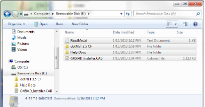
Figure 34: Installation Folder Contents
Copy the file, "GK604D_Installer.CAB" from the installation folder to the HHD system root folder. From the HDD, navigate to the system root folder using File Explorer (see Figure 35) and tap the file, "GK604D_Installer" to execute the installer.
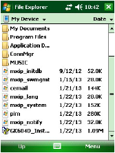
Figure 35: GK-604D Installer at Root of HDD
If there is a storage card installed in the HHD then the user will be prompted to choose the location for the installation (see Figure 36). It is recommended that "Device" be selected then tap "Install" with the stylus to initiate the install process.
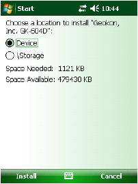
Figure 36: GK-604D Install Screen
The file, GK604D_Installer.CAB can be now deleted from the system root folder to free up memory. The GK-604D IRA is now installed and its icon should appear in "Start->Programs" (see Figure 37).
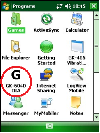
Figure 37: GK-604D IRA Icon in Start->Program
3.5Starting the Inclinometer Readout the First Time
The readout software is launched by tapping the Start button (or clicking on Programs) and then selecting the GK-604D IRA icon (shown on the right).
If the application fails to launch and the message, "This application requires a newer version of the Microsoft .NET Compact Framework than the version installed on this device", is displayed then the .NET Compact framework that is included in the installer "Zip" file should be installed. The .NET Compact Framework installer is called "NETCFv35.wm.arm4i.cab" and is located in a folder called "dotNET 3.5 CF" (see Figure 34). Installation is very similar to installing the GK-604D IRA.
A companion package for the .NET Framework, "NETCFv35.Messages.EN.wm.cab", should also be installed at this time and is in the same folder.
When starting the GK-604D Inclinometer Readout Application (GK-604D IRA) for the first time, you will be prompted to create a workspace name (see Figure 38). The workspace name can be any combination of letters and numbers and should be descriptive in nature. After creation, this name will be displayed in the Project Explorer window.
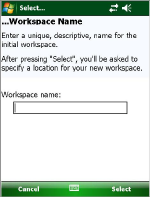
Figure 38: Select Workspace Name
Once the name for your workspace is selected, you will be prompted to choose or create a folder on your PC where all the workspace elements will be stored (see Figure 39). The default workspace location is in a folder named the same as the workspace name, under a special shared folder reserved for workspaces. For Windows Mobile devices, this folder is located at: \Application Data\Geokon\GK-604D\Workspaces.
GK-604D IRA appends the name of the new workspace to this shared folder and uses it as the default location for the new workspace. The user is free to select their own location, either by entering it directly, or the Browse button ( ) may be used to navigate to a different folder location or to create a new folder.
This workspace location will be stored in the GK-604D IRA configuration for subsequent application access. After workspaces are created, all future user access to workspaces is always by name.
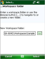
Figure 39: Select Workspace Folder
Note: If the newly selected workspace folder contains an existing workspace, GK-604D IRA will display a dialog prompt asking the user if they want to import the workspace as is or to rename it with the previously specified new workspace name (see Figure 40).
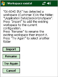
Figure 40: Workspace Exists
Much like what was done for the initial workspace, a probe library also needs to be created before the application can fully launch. After specifying the workspace folder, you will be prompted to create a probe library name (see Figure 41). The probe library name can be any combination of letters and numbers and should be descriptive in nature. After creation, this name will be displayed in the Project Explorer window.
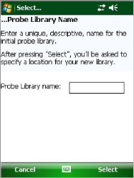
Figure 41: Select Probe Library Name
Once you have selected the name for your probe library, you will be prompted to choose or create a folder on your PC where all the probe library elements will be stored (see Figure 42). The default probe library location is in a folder named the same as the probe library name, under a special shared folder reserved for probe libraries. For Windows Mobile devices this folder is located at: \Application Data\Geokon\GK-604D\Probe Libraries
GK-604D IRA appends the name of the new probe library to this shared folder and uses it as the default location for the new probe library. Select a different location either by entering it directly, or using the Browse button ( ) to navigate to a different folder location or to create a new folder. This probe library location will be stored in the GK-604D IRA configuration for subsequent application access. After probe libraries are created, all future user access to probe libraries is always by name.
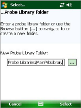
Figure 42: Select Probe Library Folder
Note: If the newly selected probe library folder contains an existing probe library, GK-604D IRA will display a dialog prompt asking the user if they want to import the probe library as is or to rename it with the previously specified new workspace name (see Figure 43).
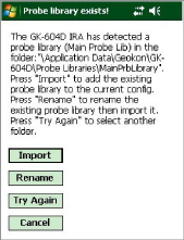
Figure 43: Probe Library Exists
After the initial workspace and probe library are created the GK-604D IRA will open, displaying the newly created workspace and probe library (see Figure 44). New project(s) and hole configurations may be added to your workspace as well as adding new probes (settings) to the new probe library.
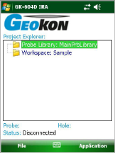
Figure 44: Empty Workspace and Probe Library