In the geotechnical field inclinometers are used primarily to measure ground movements such as might occur in unstable slopes (landslides) or in the lateral movement of ground around on-going excavations. They are also used to monitor the stability of dams, embankments, slurry walls, the disposition, and deviation of driven piles or drilled boreholes and the settlement of ground in fills, embankments, and beneath storage tanks (using horizontal inclinometers).
In all these situations it is normal to either install a casing in a borehole drilled in the ground, to cast it inside a concrete structure, or to bury it beneath an embankment or structure (for horizontal inclinometer applications). The inclinometer casing has four orthogonal grooves (see the figure below) designed to fit and position the wheels of a portable inclinometer probe (see Figure 2) within the longitudinal axis of the casing. This probe, suspended on the end of a signal cable connected to a readout device, is used to survey the inclination of the casing with respect to vertical (or horizontal) and in this way to detect any changes in inclination caused by ground movements, when compared to an established baseline survey measurement.
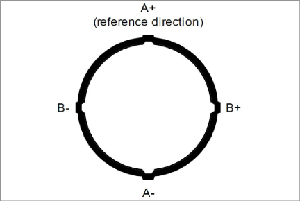
Figure 1: Inclinometer Casing (End View)

Figure 2: Inclinometer Probe
The probe itself contains two MEMS (Micro Electro-Mechanical Sensor) accelerometers, which flex when acted on by the force of gravity. Since the output voltage is proportional to the sine of the angle of inclination, the output is also proportional to horizontal deviation of the borehole (or the vertical deviation of a horizontal installation).
In order to obtain a complete survey of the ground around the installed inclinometer casing it is necessary to take a series of tilt measurements along the casing. Typically, an inclinometer probe has two sets of wheels separated by a half-meter / two feet. A casing survey would begin by lowering the probe to the bottom of the casing and taking a reading. The probe would then be raised at half-meter / two foot intervals and a reading taken at each interval until the top of the casing is reached. The readings thus generated are called the A+ (and B+) readings. Marks on the cable at half-meter / two foot spacing facilitate the process. The probe is then removed from the casing, rotated 180 degrees, replaced in the casing, lowered to the bottom of the borehole. A- (and B-) readings are obtained at the reading interval as the probe is raised.
Inclinometer probes usually contain two accelerometers with their axes oriented at 90 to each other. The A-axis is in line with the wheels ((see Figure 2) with the B-axis orthogonal to it. At each interval along the casing, readings from both A and B directions are measured. Thus, during the survey, as the A+, A- readings are obtained, corresponding B+, B- readings are also recorded.
During the data reduction, the two sets of readings at each depth interval (A+, A- and B+, B-) are combined (by subtracting one set of readings from the other) in such a way that the effect of any zero offset of the force balance accelerometer is minimized.
This zero offset is the averaged reading obtained from the inclinometer probe when it hangs absolutely vertical. Ideally, the offset (or bias) would be zero, but usually there is a zero offset which can change during the life of the probe. This change can be due to a sudden shock to the transducer caused by dropping or allowing it to hit too hard against the bottom of an installed inclinometer casing, but it can also be due to drift of the transducer or wear and damage of the wheels. Each probe will also have a slight offset initially, as the alignment of the sensors and wheel assemblies is not completely perfect.
Subsequent surveys of the inclinometer casing, when compared with the original survey, will reveal any changes of inclination of the casing and locations at which these changes are taking place. Analysis of the change of inclination is best performed by calculating the horizontal offset of the upper wheels relative to the lower wheels, which has produced the tilting (θ) over the reading interval (L) of the survey (usually the 61 cm (2') wheelbase of the probe). At each position of the inclinometer, the two readings taken on each axis (A+, A- and B+, B-) are subtracted from each other leaving a measure of sine. This value is then multiplied by the reading interval (L) and the appropriate factor to output horizontal deflection in engineering units (see Figure 3).

Figure 3: Inclinometer Survey Description
When all these incremental horizontal deflections are accumulated and plotted, beginning at the bottom of the borehole, the net result is to produce a plot of the change in horizontal deflection between the time of the initial survey and the time of any subsequent survey. From such a deflection plot, it is easy to see at which depth the movement is occurring and its magnitude (see Figure 4).
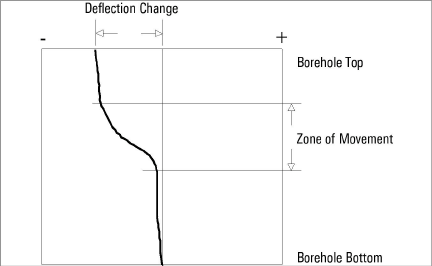
Figure 4: Plot of Borehole Deflection
Other methods of analysis can be used to assist with evaluation of the data and inclinometer casing condition. For example, using a single set of data, a profile of the borehole can be created to evaluate verticality of the casing. In addition, a plot can be made of the actual change in reading (inclination) at each measurement depth increment. A plot of this nature reveals the depths at which movement is occurring.
One other analysis is the Check Sum (or Instrument Check) which can be used to measure the quality of the survey data.
The quality of the data can be impaired by any or all the following:
■Skipping over or duplicating a reading.
■Not allowing the inclinometer enough time to come to rest before taking a reading.
■Not allowing enough time to allow the probe to reach temperature equilibrium before commencing the survey.
■Malfunction of the probe, cable, or readout device. This may be the result of shock, moisture, low battery conditions, opens or shorts in the cable or probe, etc.
■Carelessness when positioning the wheels so that the probe wheels do not rest on the same part of the casing from one survey to the next.
■Positioning the wheels so that they fall right on top of a casing joint, causing the reading to be unstable or simply erroneous.
The Check Sum analysis is performed by adding the A+ and A- readings or the B+ and B- readings. When this is done, the part of the reading due to the tilt is eliminated, leaving only a value that is equivalent to twice the zero offset of the inclinometer transducer.
The following is a synopsis of the steps involved in taking a survey of the inclinometer casing (see Section 4.3.1 for more details on setting up the readout device):
1.Use a clean working surface. If necessary, create a clean surface by placing a tarp around the top of the inclinometer casing. This reduces potential for debris to be collected on the inclinometer equipment and transmitted into the casing.
2.Attach the cable to the probe making sure that the connector is clean and the O-ring undamaged. Replace the O-ring if damaged. Tighten the connector handtight to ensure that the O-ring is compressed and watertight.
3.Attach the pulley assembly to the top of the casing. If using a casing extension, attach the pulley assembly to the top of the extension. Use of the pulley assembly is highly recommended, as it reduces fatigue on the user during monitoring and it helps provide repeatable and consistent placement of the probe at each reading interval, which improves measurement accuracy.
4.Align the probe so that the uppermost wheel fits into the casing groove that faces the direction of the anticipated movement (in the case of a slope this would be downhill, or, in the case of a shoring wall, in the direction of the excavation.
5.Remove the wheel from the pulley assembly. Compress the wheel assemblies as the probe is introduced into the casing, and lower the inclinometer probe into the casing. Slowly lower the probe and cable down through the casing, and be careful not to let the probe strike against the bottom of the hole, to reduce potential for damage to the probe.
6. Place the wheel into the pulley assembly and lift the inclinometer until the first cable marker passes the cleat on the pulley assembly (or sits in the cable hold if a cable hold is being used). Allow for at least 6 inches of clearance from the bottom of the probe to the bottom of the casing. If using telescoping sections in the casing, allow for an additional 6 inches of clearance for each telescoping section installed.
7. Allow the probe to rest in this position for about 10 minutes. This allows the electronics in the probe to acclimate to the temperature in the casing and will reduce the potential for bias-shift errors caused by thermal differences in the probe between the first and second pass.
8. During this 10 minute period, switch on the FPC-2, turn on the Remote Module (blue light blinking), then launch the GK-604D IRA. Follow the instructions for setting up a new casing as indicated in Section 3.2. For new casings, take note of the starting depth indicated on the cable (typically where the cable is supported) and the reading intervals (half-meter / two foot). End depth is zero by default, and if a reading of zero cannot obtained, based on the configuration, then Section 4.3.5 provides methods to deal with this in the data files.
9. If an existing casing, with a previously established configuration file, navigate to that file location and select it. After verifying that the handheld unit has connected to the probe, click on the Live Readings menu and observe the inclinometer reading.
10. Make sure that the GK-604D IRA is set to Data Set 1. Take the first reading, pull up on the cable until the next cable marker sits into the cleats on the pulley assembly, (or in the cable hold), and, after about two seconds or the readings have stabilized, take another reading.
11. As the cable is being pulled up and out of the casing, place on the tarp (or clean surface) to the side of the borehole. The cable should be collected in a figure eight-shaped arrangement on the ground (or tarp). This process will reduce the potential for damage of the cable. Do not wind the cable back onto the reel during this process, as repeated and continued winding of this cable in the same direction will cause the cable to spiral and lead to kinking or damage to the internal leads of the cable.
12. Continue in this way until the top marker is reached, then remove the wheel from the pulley assembly, and pull the inclinometer probe out of the hole.
13. Rotate the probe 180 degrees, so that the uppermost wheel is aligned with the grooves of the A- direction (opposite of the first pass). Again, carefully lower it to the bottom of the hole, and then pull the cable up to the first reading depth.
14. Allow for a few minutes (up to 5 minutes) for the probe to stabilize. The probe should be fairly acclimated to the temperature in the casing, unless the probe was out of the casing for an extended period following the first pass. Tap the Dataset 1 button to select "Data Set 2".
15. Repeat steps 10 through 12.
16. Tap on Menu->Exit Live Readings to save the data, and then shut down the readout and the reel.
17. Disconnect the probe from the signal cable, and attach protective caps to the probe and the cable. Collect the pile of inclinometer cable and flip it over on the tarp. Retract the cable back onto the reel. If the cable is difficult to manage and get back on the reel without causing kinked sections, it is suggested to lower the cable (without probe and with end cap) back into the inclinometer casing to allow it to release some of the twist it may have developed, and then wind in up on the reel.
18. Wipe down the probe after each use. Spray a light lubricant (WD-40, or similar) on the springs, wheel assemblies, and yokes prior to placing in the protective carrying case. Do not apply this lubricant to the electrical connection end of the probe. Grease the wheel bearings as indicated in Section 7.
19.Select the size of pulley assembly, (or cable hold), that matches the inclinometer casing and place it inside the top of the casing. Lift the inclinometer until the first cable marker passes the clamps on the pulley assembly (or sits in the cable hold if a cable hold is being used).
20.Switch on the FPC-2, turn on the Remote Module (blue light blinking) then launch the GK-604D IRA. After verifying that the handheld unit has connected to the probe, click on the Live Readings menu and observe the inclinometer reading. Wait until the probe temperature has stabilized and the reading does not change.
21.Make sure that the GK-604D IRA is set to Data Set 1. Take the first reading, pull up on the cable until the next cable marker sits just above the cable grips on the pulley assembly, (or in the cable hold), and, after a short pause, take another reading.
22.Continue in this way until the top marker is reached, then remove the pulley assembly, (or cable hold), and pull the inclinometer out of the hole.
23.Twist the probe through 180 degrees then lower it to the bottom of the hole. Tap the Dataset 1 button to select "Data Set 2".
24.Repeat steps three through six.
25.Tap "Menu->Exit Live Readings" to save the data.