To avoid end effects, strain gauges should be placed away from the ends of struts where they may be influenced by localized clamping or bolting distortions. For most structural members a distance of five feet is sufficient. Alternatively, end effects may be of some interest because they add to the load-induced effects, and may be large enough to initiate failure at the ends of the structural member, rather than in the middle.
Arc welding close to the gauges can cause very large localized strains in the steel member. Welding studs onto soldier piles to support lagging, shotcrete reinforcing mesh, etc., can cause big strain changes. This is also true of welding cover plates, protective channels, etc., over the gauges and cables. Always take gauge readings before and after any arc welding on the steel structure so that corrections can be applied to any apparent strain shifts.
In the case of a steel structure, a strain gauge measures the strain at one point on the surface, and this would be sufficient if it could be guaranteed that no bending was occurring in the member. In practice, this will only occur near the center of long thin members subjected to tensile loads. Elsewhere, bending moments are the rule rather than the exception, and there will be a neutral axis around which bending takes place.
Since bending effects must be taken into account, more than one strain gauge is required at each cross section of the structural member. For a complete analysis at least three gauges are required, and very often more than that are needed. On a circular pipe strut, three gauges spaced 120 degrees apart around the periphery of the strut would suffice (see Appendix G). On an H pile or I-beam, at least four strain gauges would be required. On sheet piling, two gauges back to back on either side of the pile would be sufficient. Where a member is subjected to bending and only the front surface is accessible, e.g., a steel tunnel lining or the outside of sheet pilings, the bending moments can be measured by installing two vibrating wire gauges at different distances from the neutral axis (see Appendix H).
Consider the example of an I-beam, as shown in the figure below.
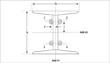
Figure 12: Strain Gauges Mounted on Central Web
It is always best to locate gauges in pairs, one on each side of the neutral axis corresponding to the section of the I-beam to which the gauge is attached. This, along with locating the gauges on the web making them easy to protect from accidental damage, is why the configuration shown above is preferable.
Note: This configuration is not recommended for tunnel arches.
Strain gauges mounted on the central web can measure axial strain as well as bending moments around both XX and YY axis. In this configuration, four strain gauges (1, 2, 3, and 4 in the previous figure) are welded back to back in pairs on the central web. The gauges are at a height (d) above the center of the web (Axis YY) and at a distance (c). The width of the I-beam flange is represented by 2b and the depth of the web by 2a.
The axial stress is given by averaging the strain reading from all four strain gauges and multiplying by the modulus, as shown in the equation below.
|
σaxial = |
(ε1+ε2+ε3+ε4) |
x E |
|
4 |
Equation 1: Axial Stress Calculation
The stress due to bending is calculated by looking at the difference between pairs of gauges mounted on opposite sides of the neutral axis. Thus, the maximum stress due to bending around Axis YY is given by:
|
σyy = |
(ε1+ε3) - (ε2+ε4) |
x |
b |
x E |
|
2 |
d |
Equation 2: Stress Due to Bending on Axis YY
The maximum stress due to bending about Axis XX is given by:
|
σxx = |
(ε1+ε2) - (ε3+ε4) |
x |
a |
x E |
|
2 |
c |
Equation 3: Stress Due to Bending on Axis XX
σmaximum = σaxial + σxx + σyy
In all of the above calculations, pay strict regard to the sign of the strain. A positive change is tensile and a negative change is compressive.
Note that the total strain, at any point in the cross section, is the algebraic sum of the bending strains and the axial strain. The strains in the outer corners of the flange can be much higher than the strains measured on the web, and that failure of the section can be initiated at these points, hence the importance of analyzing the bending moments.
The above consideration would seem to lead to the conclusion (from the point of view of obtaining the best measurement of the maximum strains) that the ideal location for the strain gauges would be on the outer corners of the flanges, as shown in the figure below. However, this configuration makes it difficult to protect the gauges and cables from accidental damage. In addition, a serious problem can arise from the fact that each of the four gauges can be subjected to localized bending forces, which affect only one gauge, but not the others. For example, it is not uncommon for welding to take place at points close to a strain gauge; this often produces large strain changes in the gauge. It is also not uncommon for local blocking (e.g., tunnel arch supports) and the addition of struts, to cause strain changes on a single nearby gauge.
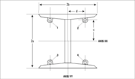
Figure 13: Strain Gauges Mounted on Flanges
For reasons of economy, if it is decided that only two strain gauges per cross-section are to be used, then the configuration shown in the figure below may be used. This configuration will give the axial strains and the bending moment around the minor YY axis only.
14:
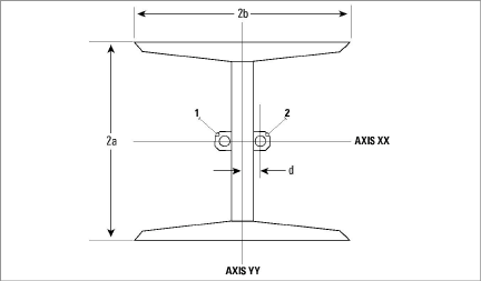
Figure 14: Axial Strain Measurement/Bending Moment About YY Axis
This configuration allows for easy protection of the instruments and their cables. If desired a hole may be drilled in the web so that the cable from one gauge may be passed through to the other side, allowing both cables to be protected by a single conduit.
Another possible two-gauge configuration is shown in Figure 15.
This configuration allows the calculation of the axial strains and the bending moment around the major XX axis. A disadvantage lies in that the exposed position of the gauges on the outside of the flanges requires a greater degree of protection. Also, local bending at one gauge may not be felt by the other gauge. A real world example of this was seen when welding on the exposed flange of a soldier pile close to one gauge produced large strain changes which were not felt by the other gauge on the back side of the pile.
15:
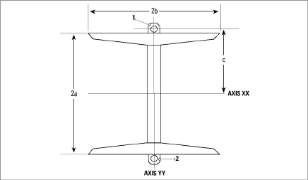
Figure 15: Axial Strain and Bending Moment About XX Axis
The configuration shown in the figure below has been used to allow the calculation of the axial strains, as well as to provide a measurement of the bending moment around the major XX axis. However, any bending around the minor YY axis will affect the reading to some extent. More importantly, there is the risk that one gauge can be affected by local bending without affecting the other gauge. This configuration is not recommended.
16:
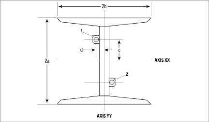
Figure 16: Axial Strain and Bending Moment About Axis XX (NOT RECOMMENDED)