Appendix E.Model 4500AR Piezometer
15:
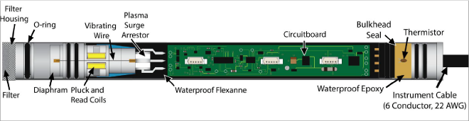
Figure 15: 4500AR Piezometer
The Model 4500AR Piezometer is designed to be used with readout systems that can read frequency but do not have the capability to pluck the VW gauge. The sensor has built-in electronics that cause the gauge wire to vibrate continuously at its resonant frequency. The output from the sensor is a five-volt DC square wave at this frequency.
A DC input voltage in the range of six to 24 volts is required to operate the gauge. The current consumption is approximately 21 mA at 12VDC. The gauge output is independent of the input voltage.
Multiple sensors powered simultaneously can be read at quite fast rates (up to five sensors per second) and dynamic measurements on a single sensor can be made up to approximately 20Hz.
The gauge is installed in the field in the same way that the Model 4500 standard piezometer is installed (see Section 3 and Section 4).
4500AR Piezometer Wiring is shown in Table 8. The three pair cable is wired in pairs, with each pair comprising one colored and one black lead.
|
Wire Color |
Function |
|
Red |
+6–24 VDC Power |
|
Red’s Black |
Ground |
|
White |
Output |
|
White’s Black |
Output Ground |
|
Green |
Thermistor + |
|
Green’s Black |
Thermistor – |
|
Bare |
Shield |
table 8: 4500AR Wiring Chart
Upon power up the gauge will immediately start to ring at the resonant frequency and will continue to ring until the power is removed. Continuous operation will have no effect on the gauge life.
Note: The sensor comprises two transducers: the VW pressure sensor, and a thermistor for measuring temperature. The signal from the VW transducer is a high-level frequency and it will interfere with the thermistor output if left powered during the period that the thermistor is being read. If the temperature reading is important, the power to the pressure sensor should be switched off while the thermistor reading is taken.